Construction and movements in week 4

After four weeks the project has come to an end and we can say that we have achieved most of our goals.

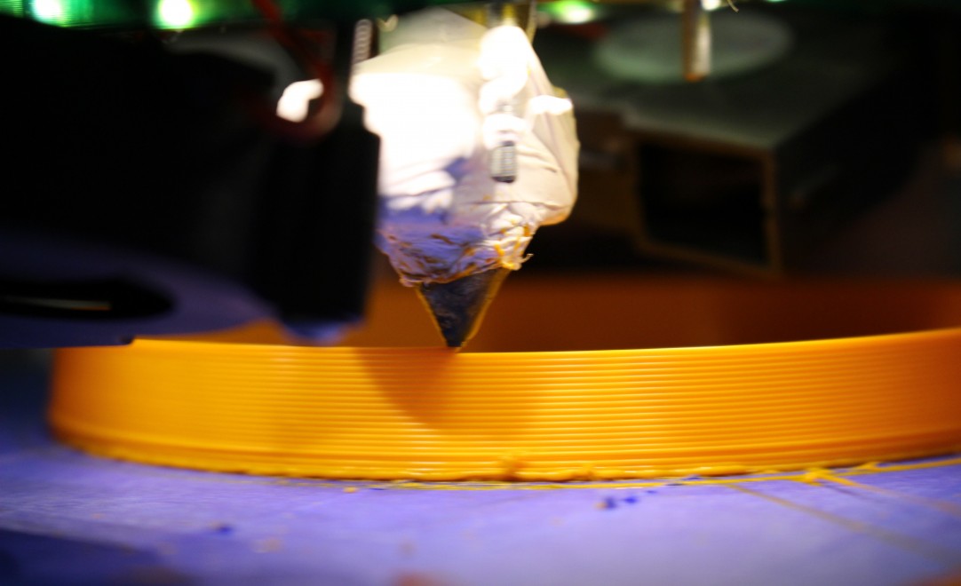
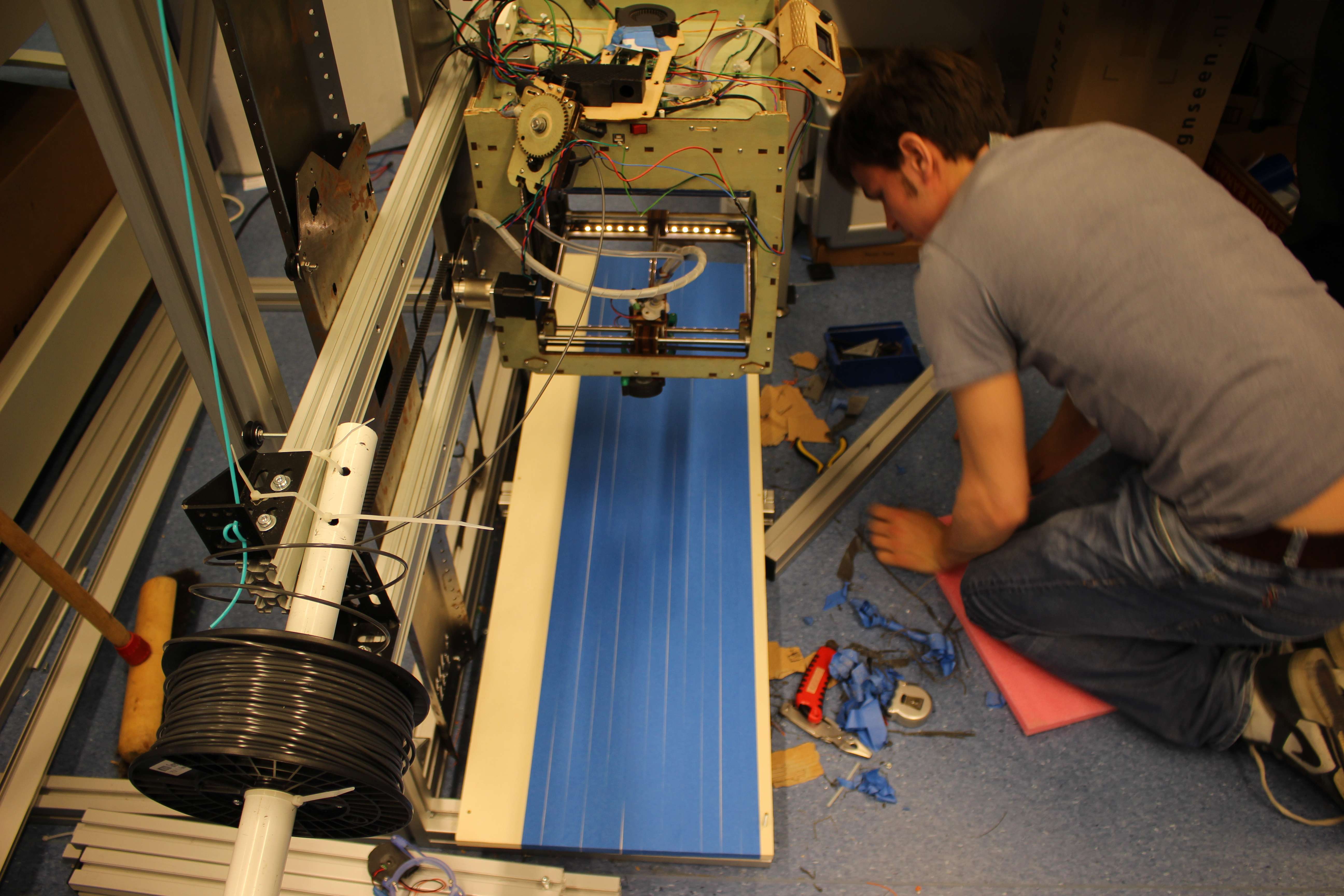
The printer is working correctly, precisely and better than we had expected. The maximum size that we can print with our particular installation is approximately 1000*800*200 mm. With some simple adjustments to the frame, we would be able to print up to 2000 mm high.

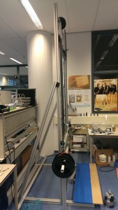
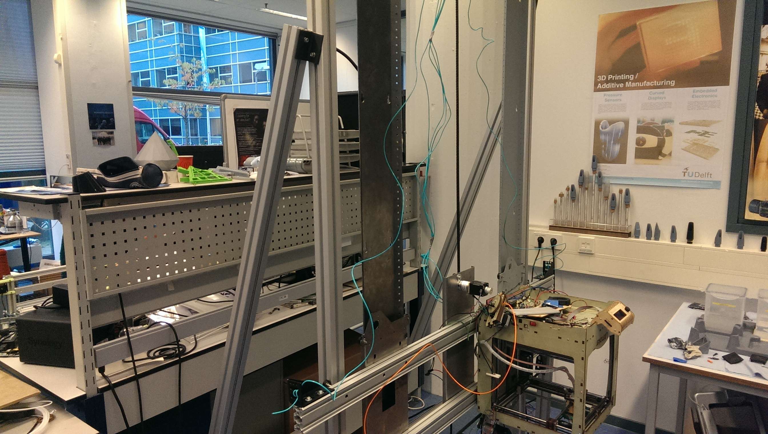
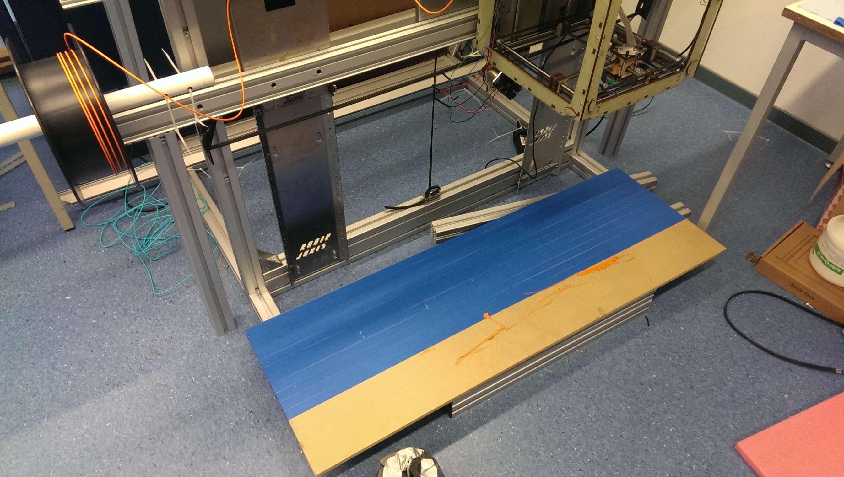
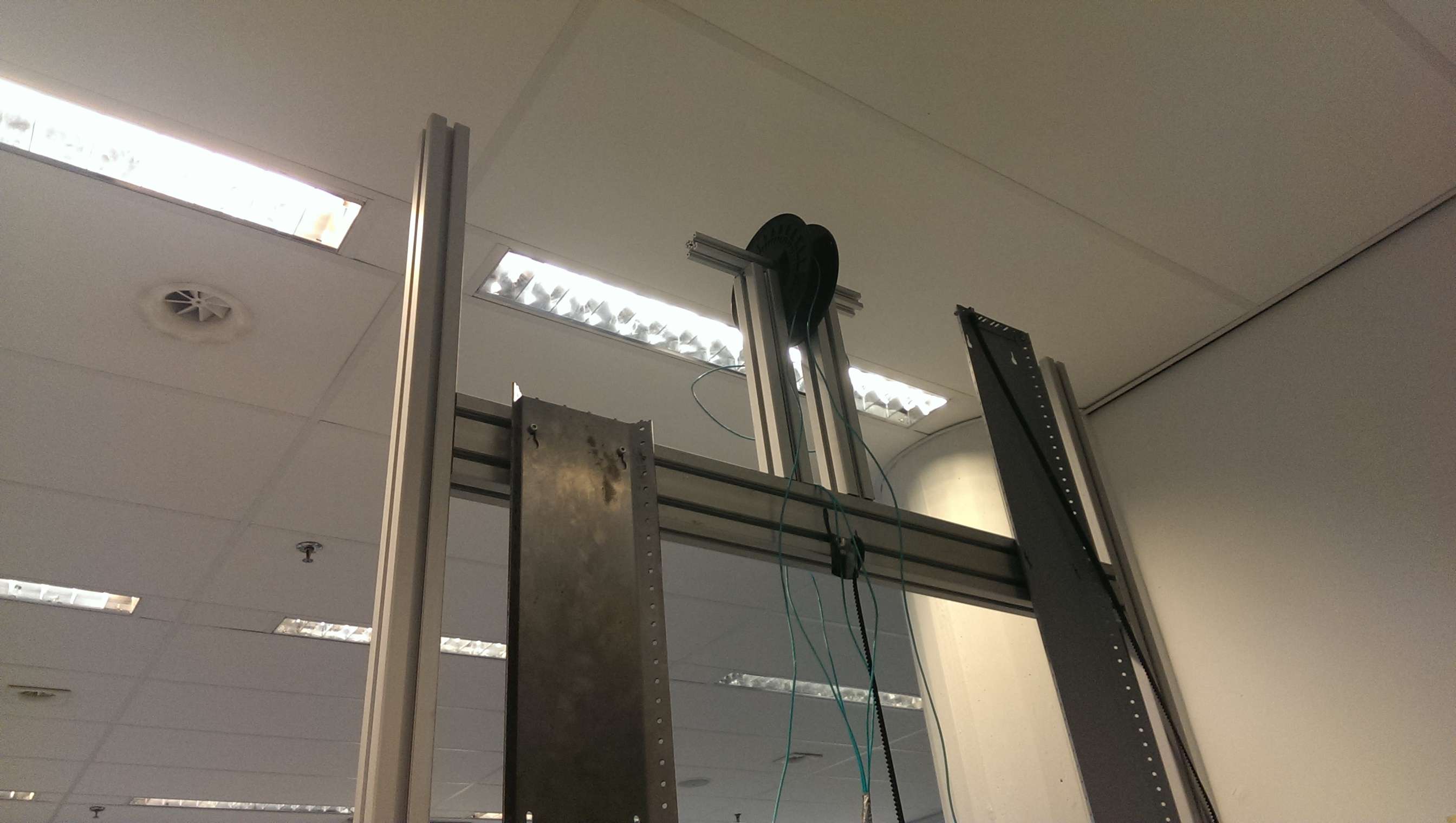
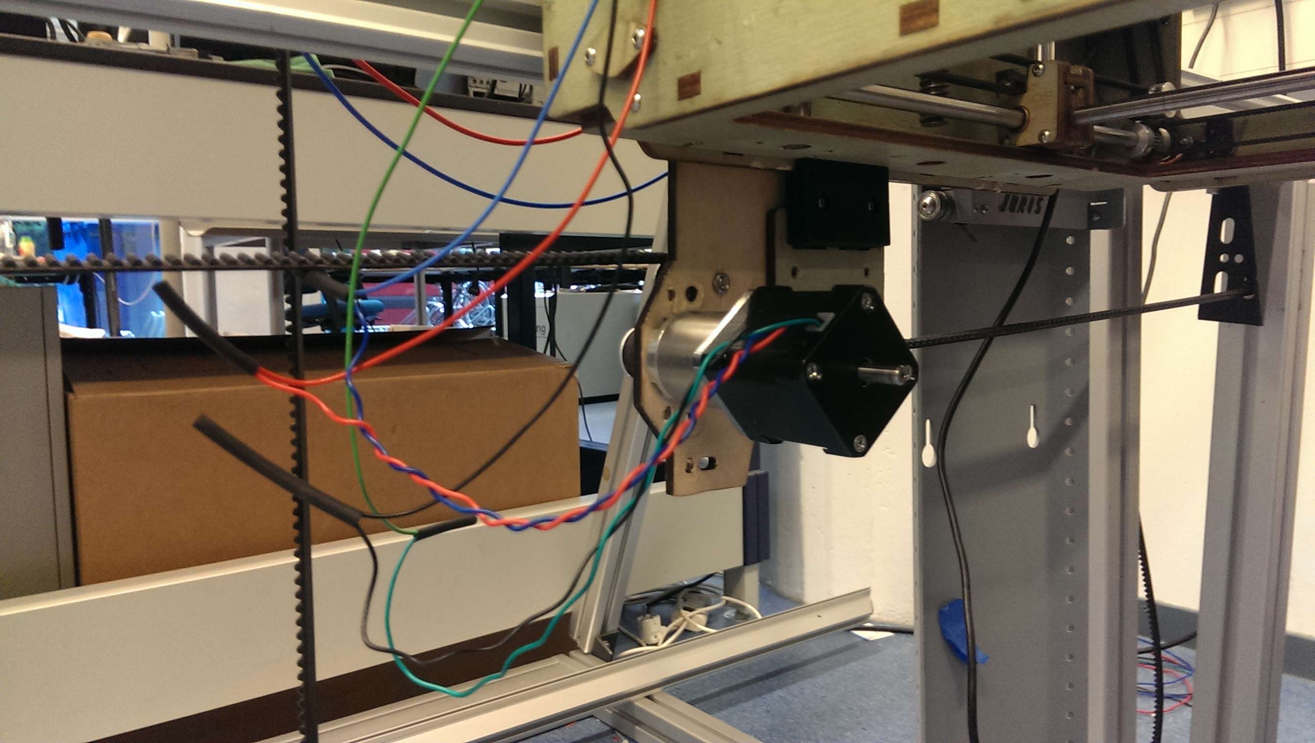
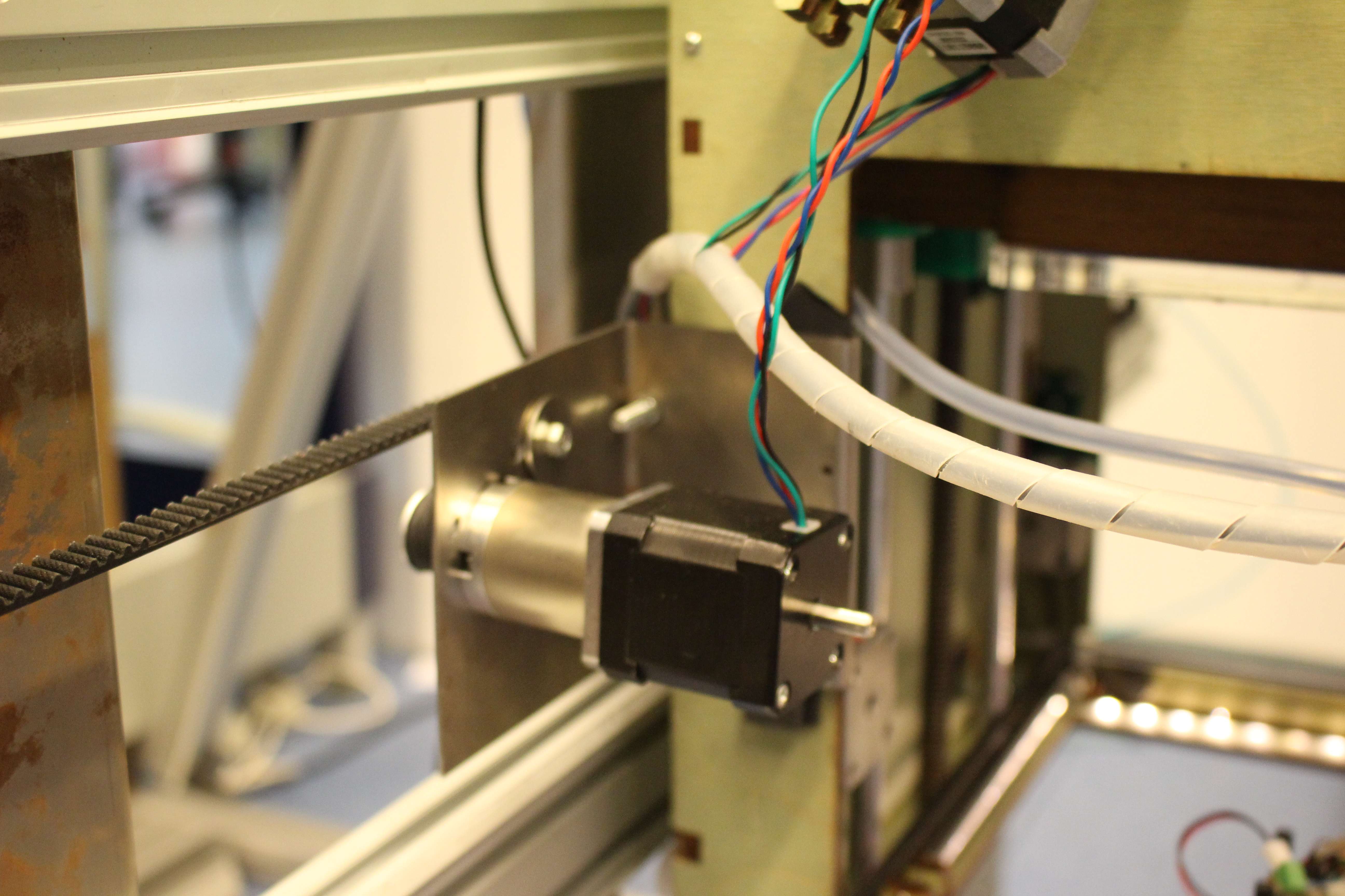
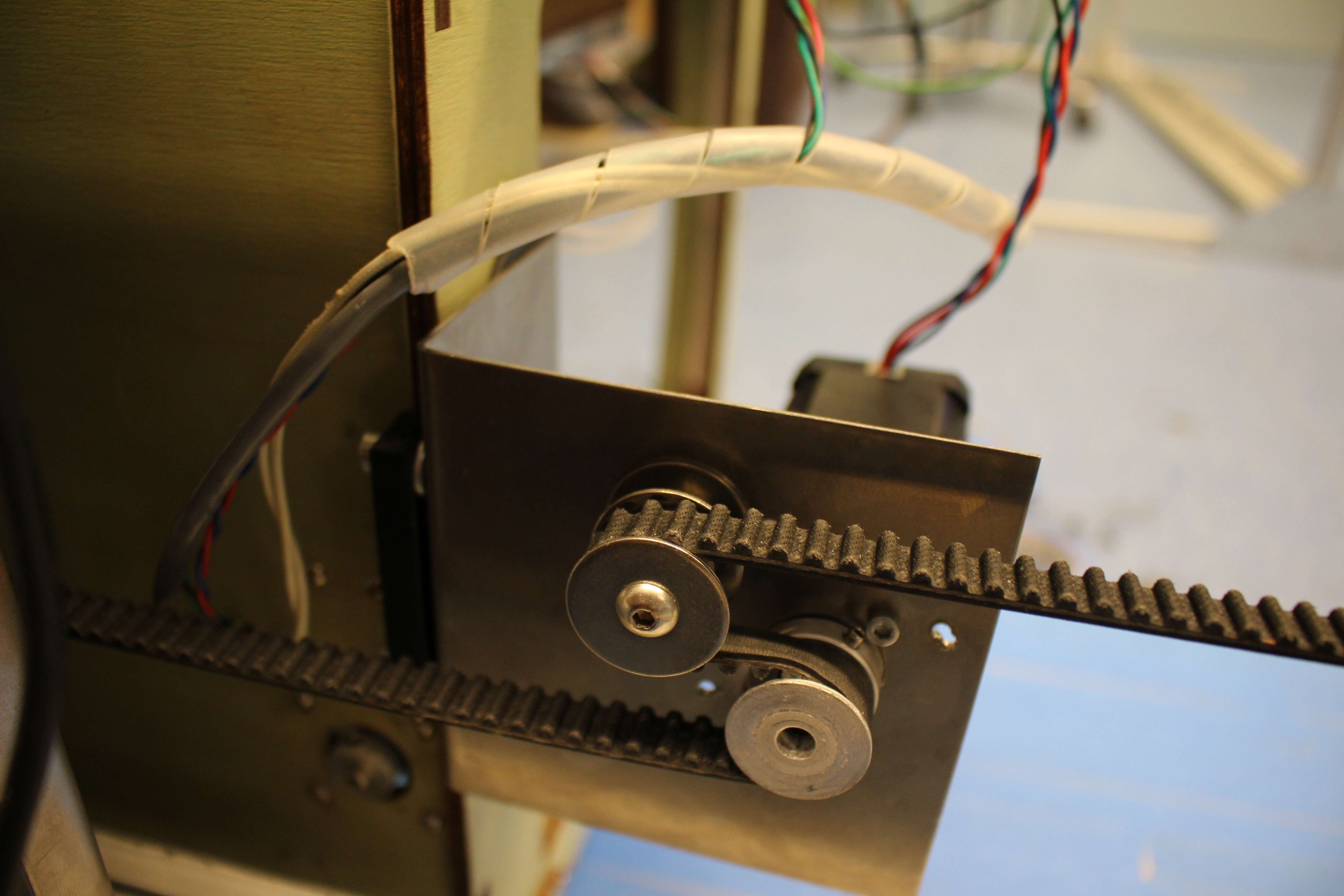
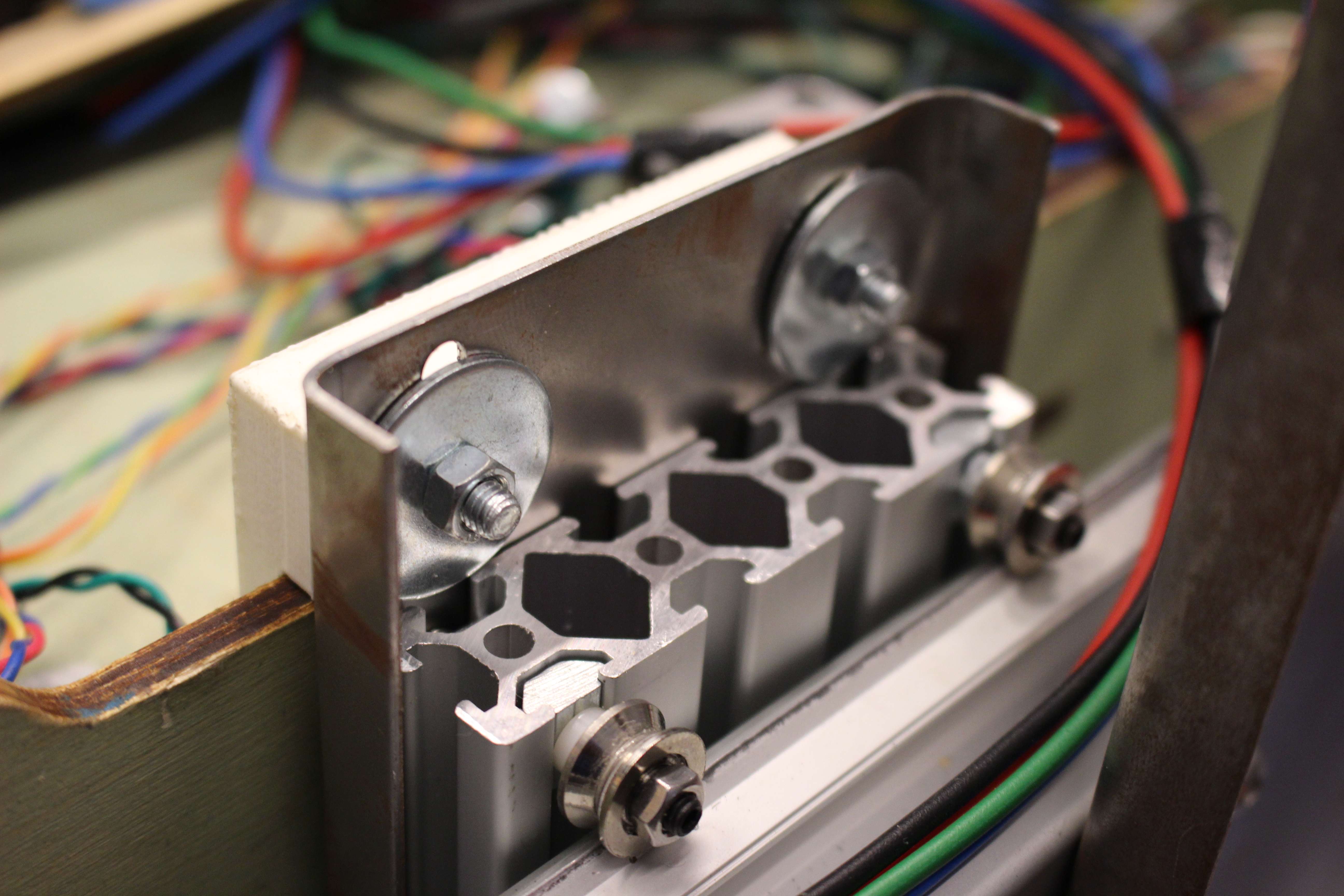
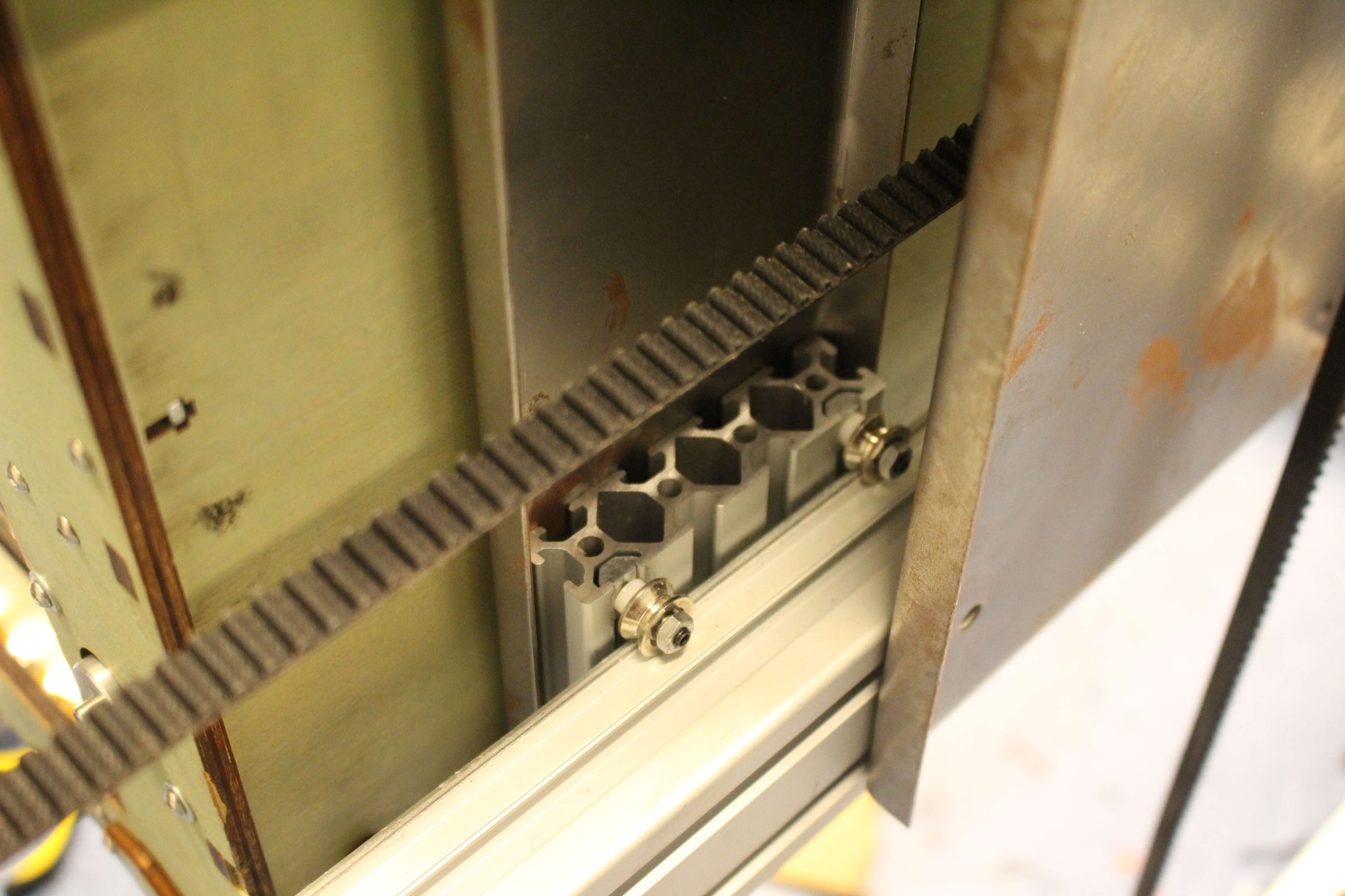
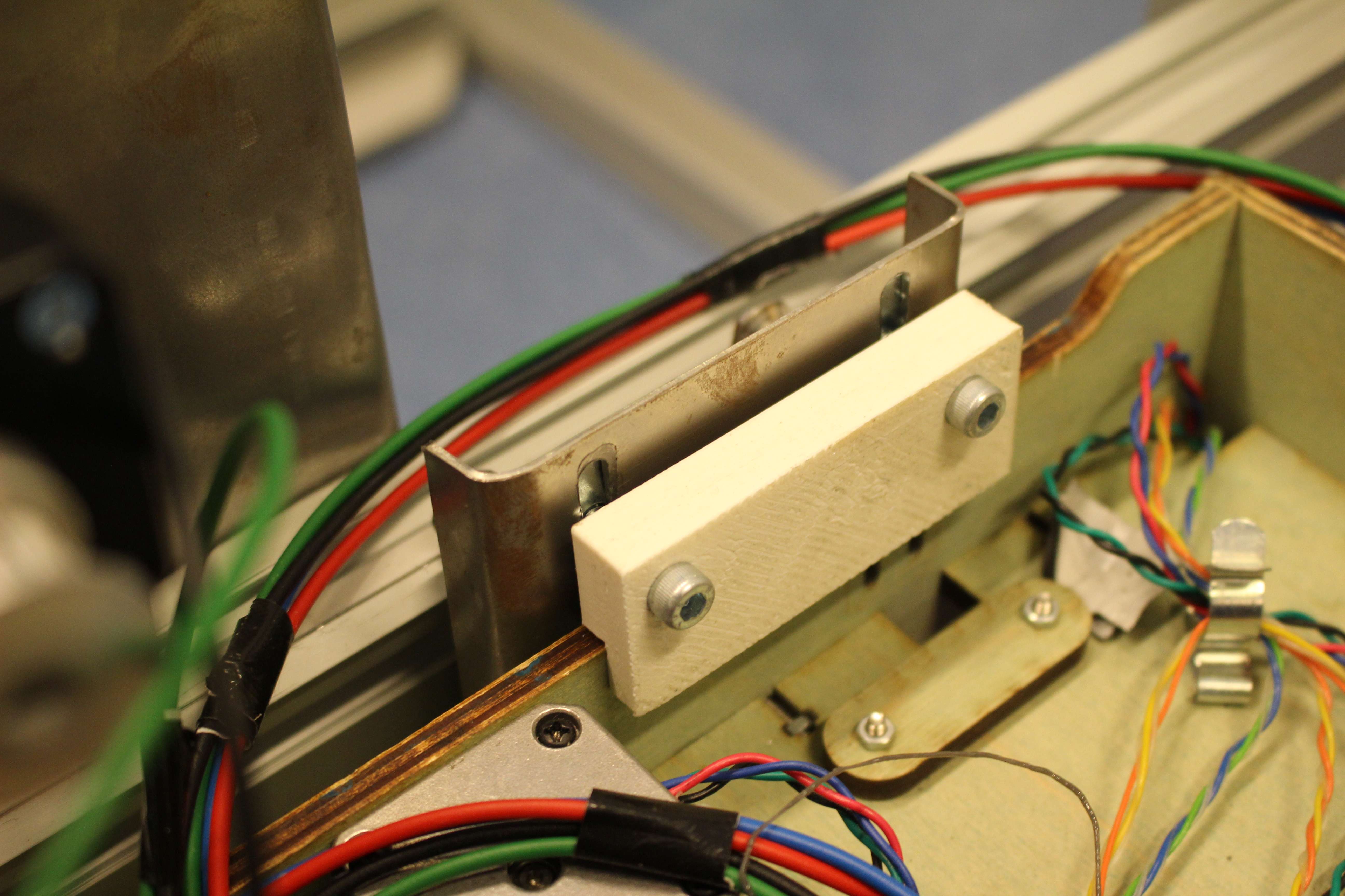
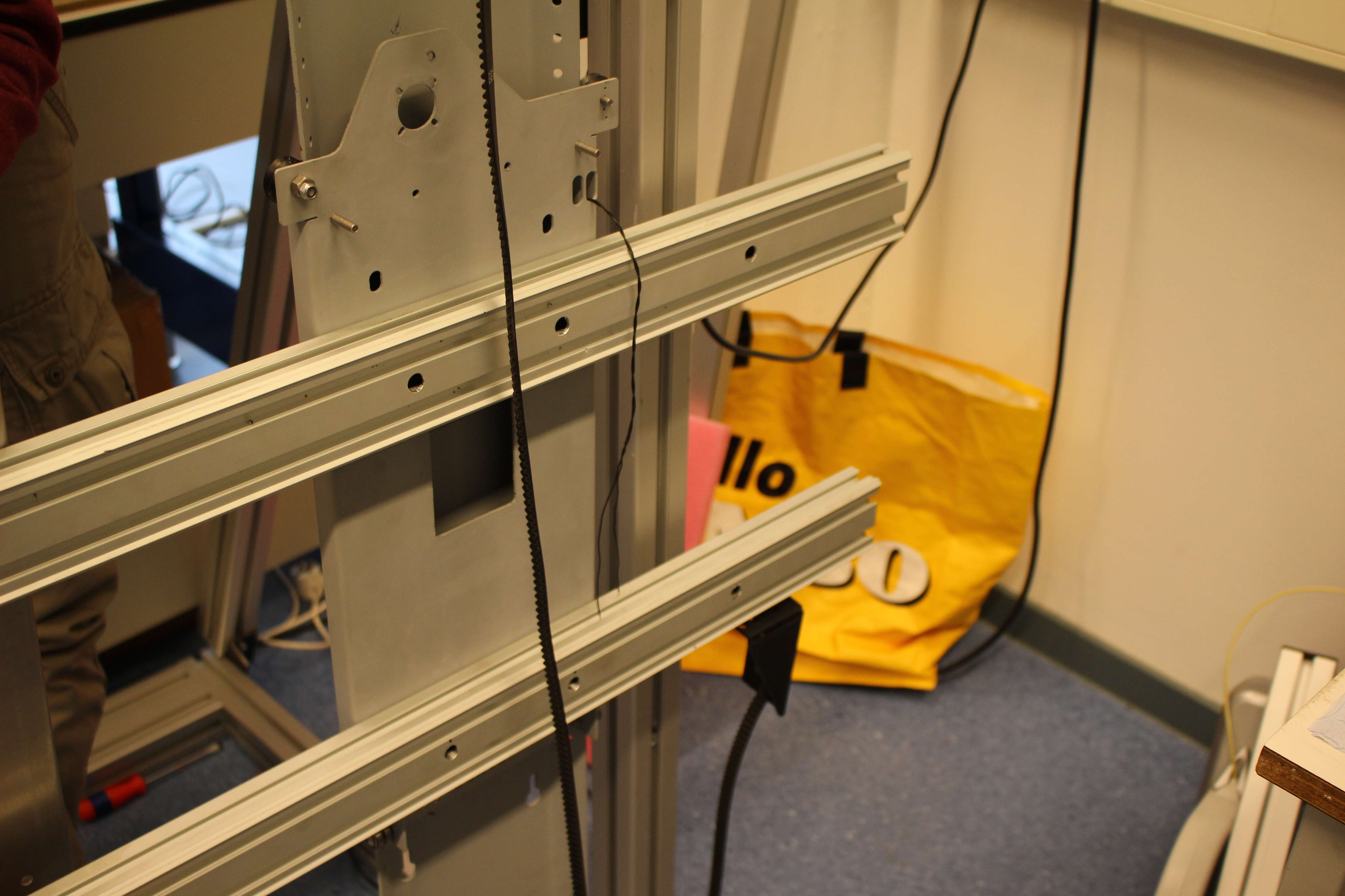
How the mechanics  look now compared to two weeks ago:

We have changed the place of steppermotor which moves the Ultimaker along the bigger X-axis. This way we are now able to print on the total Y-axis of the Ultimaker

IMAG0586 IMG_7006 IMG_6989

An other thing we have changed is the printbed. In the first three weeks we weren’t able to adjust the height of the bed as it was resting on three beams. We didn’t need a real precise flat bed, as we didn’t werent able to come close to the point that the print was effected by the bed. The printer itself was the biggest problem, for failed print. As the printer became more precise we needed find an adjustable (very) flat bed. We used a 12 mm triplex. We drilled 6 holes in the wood and used screws and bolts to adjust it. We would have prefered to use thick plexiglas which is very expensive.

IMG_7020


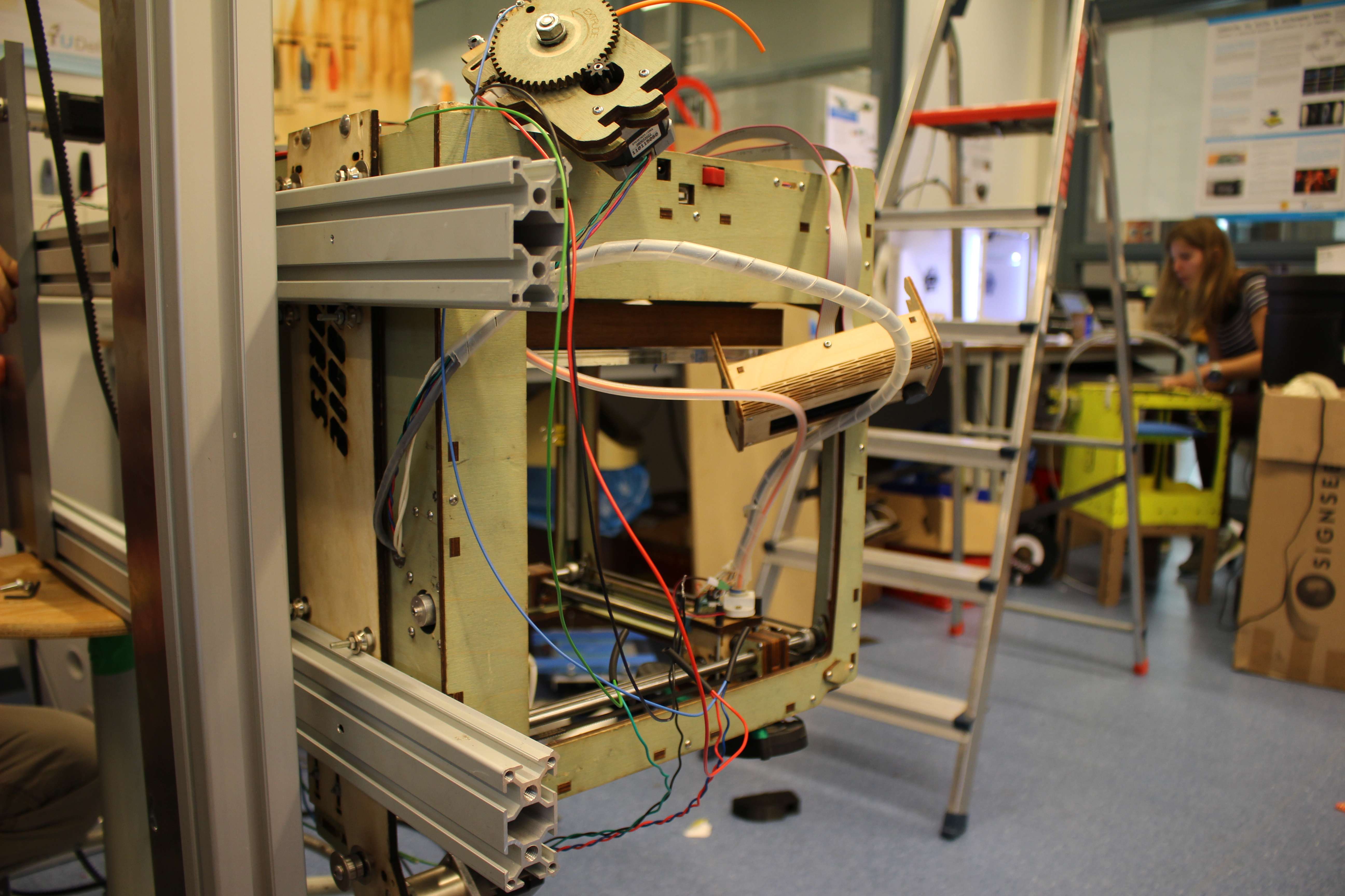
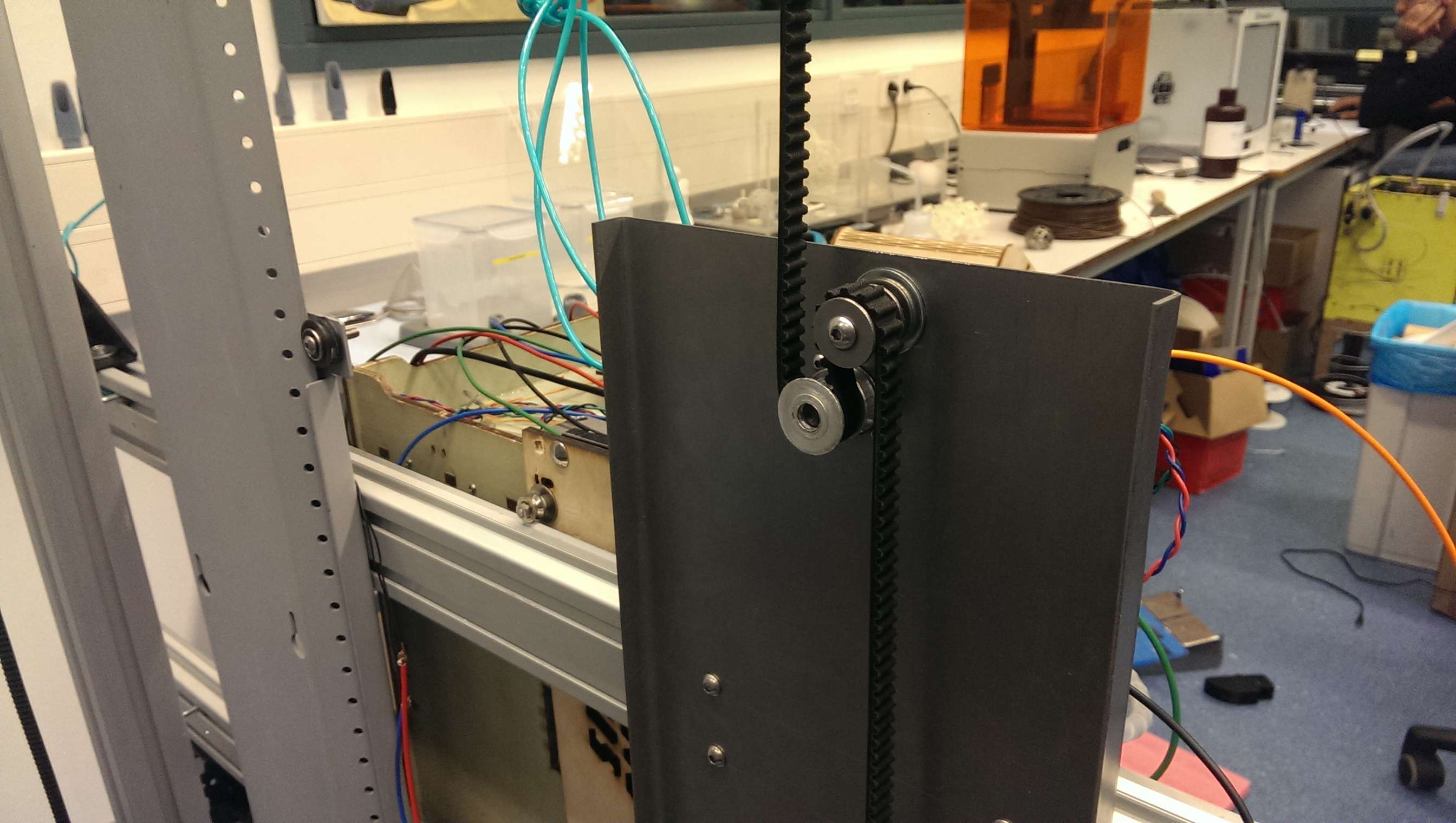
And as we told in an earlier post we also changed the way the Ultimaker was attached to the horizontal tail. We replaced the earlier used wooden plate for a steel plate. The reason for this was that the holes in which the rails were fixed, got bigger. And because of this the printer fall off the rail a couple of times. The resulting product can be seen in the picture beneath.

IMG_6988 IMG_7014 IMG_6986 IMG_6835_Kopie


This were the major adjustments in the construction of the installation. For the rest there were some little tweaks here and there.


Adjusting the printer

As the mechanical parts were installed and working, it was time to calibrate the printer to print smooth and accurate objects. As we encountered problems with the additional X-axis we decided to start working with only one x-axis. We replaced the inner X-axis with the outer axis.

This brought different problems to light. The normal acceleration of the printer head was to high for the external x-axis. The stepper motor kept slipping and moved further than it should. With every move the x-axis made, the difference with the layer beneath  became bigger.
It also didn’t help the fact that the belt on which the stepper motor moves, wasn’t tense enough.

We also had a problem with the amount of steps the stepper motor on the bigger x-axis made compared to the y-axis stepper motor inside the Ultimaker. When we noticed this problem while printing, we tried to print a square to confirm our observation. And our observation were confirmed when the Ultimaker made a rectangle instead of a square. To solve this problem we adjusted some numbers in the firmware of the printer.


IMG_6997

Here you see a test print. You see two rectangles with overlap, because of a shift that happend.

A third problem  we encountered was that the internal x-axis kept moving a little when the printer shifted from left to right and back again. Because there was no electric single to the stepper motor, there was no ‘brake’ on this axis.

We didn’t continue with the idea of working with only one x-axis, even with the fact it was very promising. As it is eventually the plan to make multiple printers work together two axes per printer are effective.

So we continued with the original plan: getting the printer to print while using two x-axes.


De constructie en aandrijving

De installatie bestaat uit de volgende onderdelen:

  • Het frame
  • de verticale rails
  • de horizontale geleiders
  • een bevestigingsplaatje voor de Ultimaker
  • de Ultimaker
  • het printbed
  • contragewicht

Het frame is gemaakt van een bepaald alumiumprofielen systeem. De verschillende balken worden op dezelfde manier aan elkaar vastgemaakt. Het is 120 cm breed en 290 cm hoog.

IMAG0581

Op het frame zijn de verticale rails bevestigd. Deze zijn ons door Joris ter beschikking gesteld.

Vervolgens zijn op de vericale rails, de twee horizontale rails bevestigd.

IMG_6835_Kopie

Om de printer over de horizontale rails te laten lopen hebben we een plankje met 8 v-wieltjes er aan vastgemaakt.

IMG_6836_kopie     IMG_6837_Kopie     IMG_6838_kopie

Verder hebben we nog het printbed en een katrol met een contragewicht.

IMAG0583 IMAG0584

Bij de benodigde bewegingen maken we gebruik van stappenmotors. Voor de verticale beweging hebben we een stappenmotor aan een stalen plaatje bevestigd en vervolgens aan de horizontale rails vastgemaakt. Deze motor wordt geholpen door een een contragewicht van ongeveer 15 kg.

IMAG0588   IMAG0591

De stappenmotor die de beweging over de vergrote x-as regelt, is onder de Ultimaker bevestigd.

IMAG0586