Sciencefair

There was only one question for the science fair: is it possible to move our xxl 3d printer to the main hall? With a dolly we moved the printer to the hall. After setting up the XXL printer we started to calibrate the print bed. While doing that we were already getting some attention by passing students and teachers. When the science fair started we were able to print with the xxl printer again. With some posters we showed our process and also the working principle of the printer. With our spare printer we showed how we were able to slice an object into parts. With this we could explain, if we would do this with the bigger printer, the printer would be relatively faster while printing an object with infill.


IMG_7037

Calibrating the printing bed

During the science fair a lot of people came by and were quiet amazed about the construction. Our mentors Joris and Dolf came by and also Wael an art student we talked with about printing a big art work.

We think the most reactions were really positive. Only one big remark was the speed of the printer. Why we did not remove the housing of the Ultimaker to make it lighter and faster?

IMG_7034

Lots of interested people

IMG_7035

Emma, explaining the project

Walking around the fair was nice as well. All the groups made some nice stuff and it looked quiet professional.

After discussing what to do with the printer, we put it back in the science lab or further research.

Conclusion

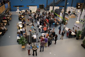
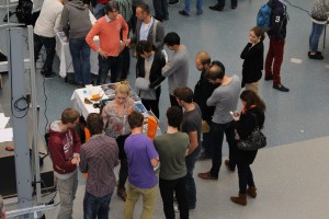
Since the Sciencefair is over and our available time has ended, we need to reflect on our project. First we will reflect on the process and the team, after that we will reflect on the construction and the software with the question: where are we now and what’s next?

Overall conclusion

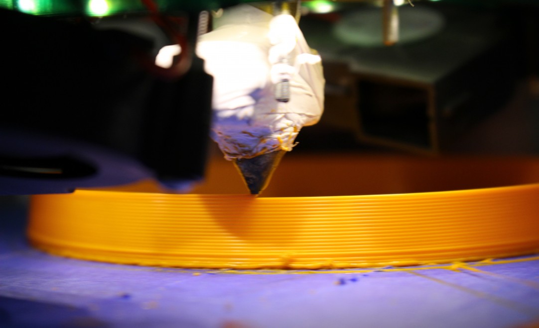
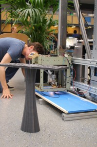
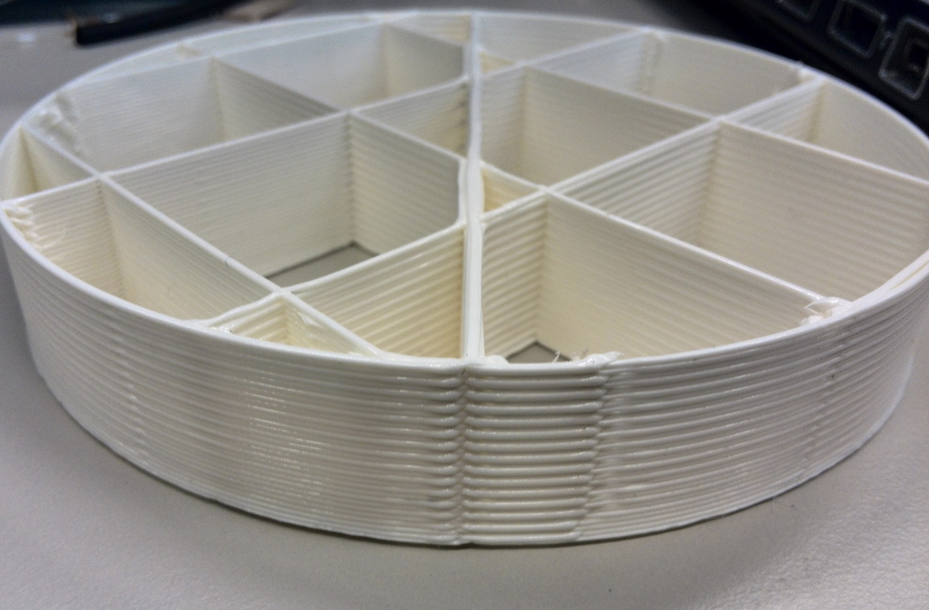
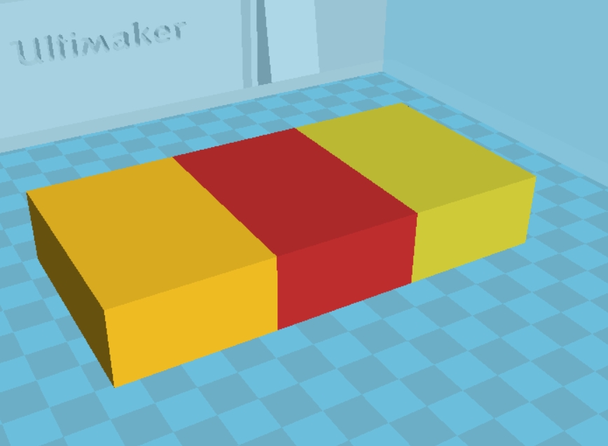
First of all, it worked! Our main goal was to get the printer to make something wider and taller than was possible before and we achieved that. We learned a lot about printing with the Ultimaker. Before we started this project, we didn’t know anything about printing with the Ultimaker at all! Besides that, we worked well together, except for some moments where we didn’t communicate perfectly. We also learned a lot about solution thinking. We were all used to calculating and sketching our ideas first, before building things. This time it was was the other way around. We could have made some more sketches, to make it work faster, but calculating was not necessary.

As mentioned before, we found it hard to plan the overall project. The first two weeks, we were working on something we wanted to work. After a chat with Dolf, we made ourselves a scheme, which helped us with getting an overview of the process and the project.

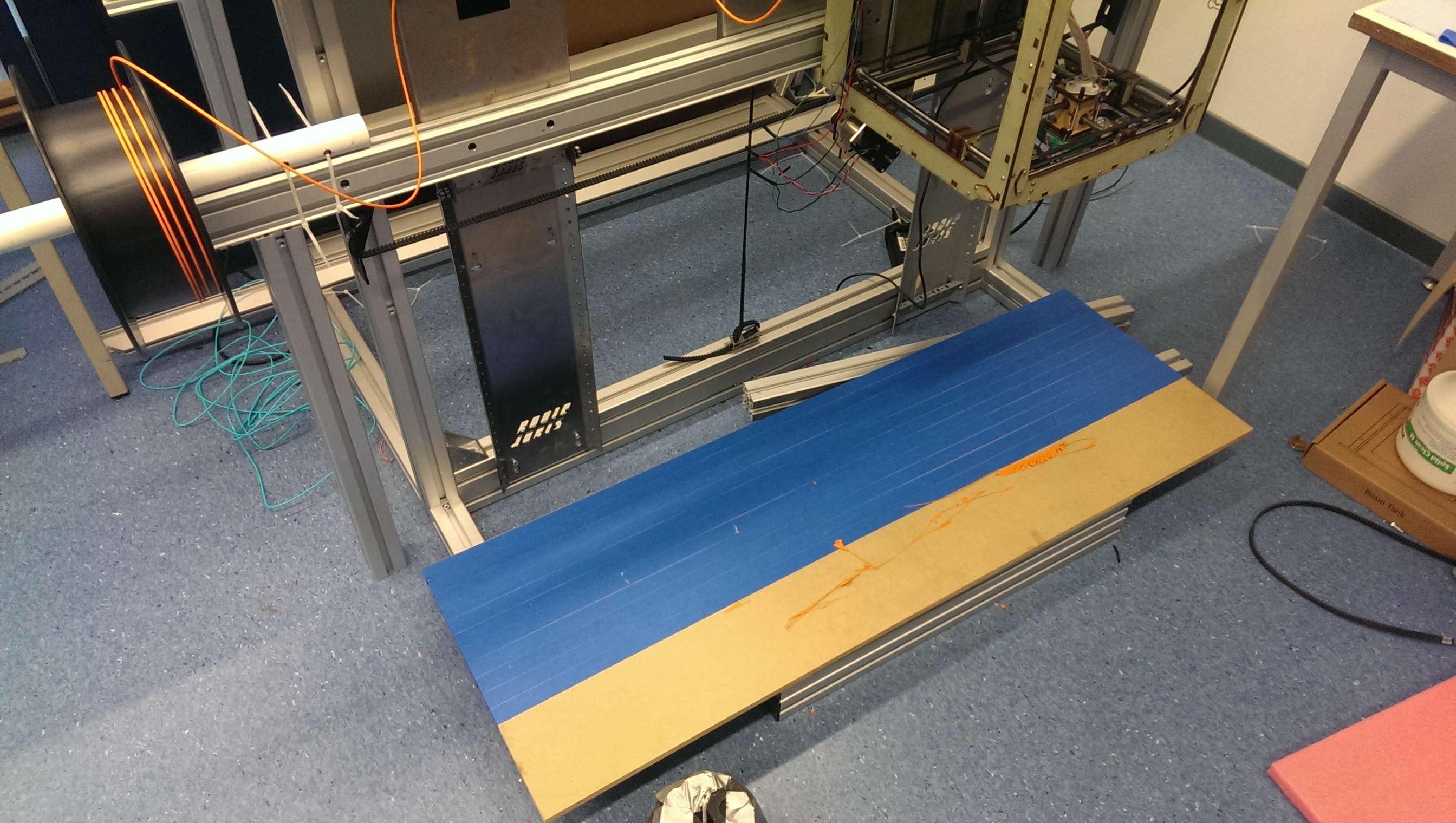
We also could have worked with a better printing bed. Our unequal printing bed didn’t help us with getting nice printing results. There are also a few more things in which we could have invested more to make it all work better. Although we choose to work with everything we had and not to buy expensive parts for our construction which lead to compromises.

Last of all: testing takes time! We tested a lot to check what was going wrong. This brought us solutions, but it also toke a lot of time. Every time the printer had to heat and go to a starting position. Besides that, the print had to run for some time before discovering problems.

So, we all think it is a pity we do not have more time to work on this project. There are a lot of things to improve and we have the first working prototype now, so actually, it should start from here!


Changes that would improve the construction and movements of the printer

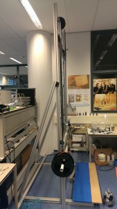
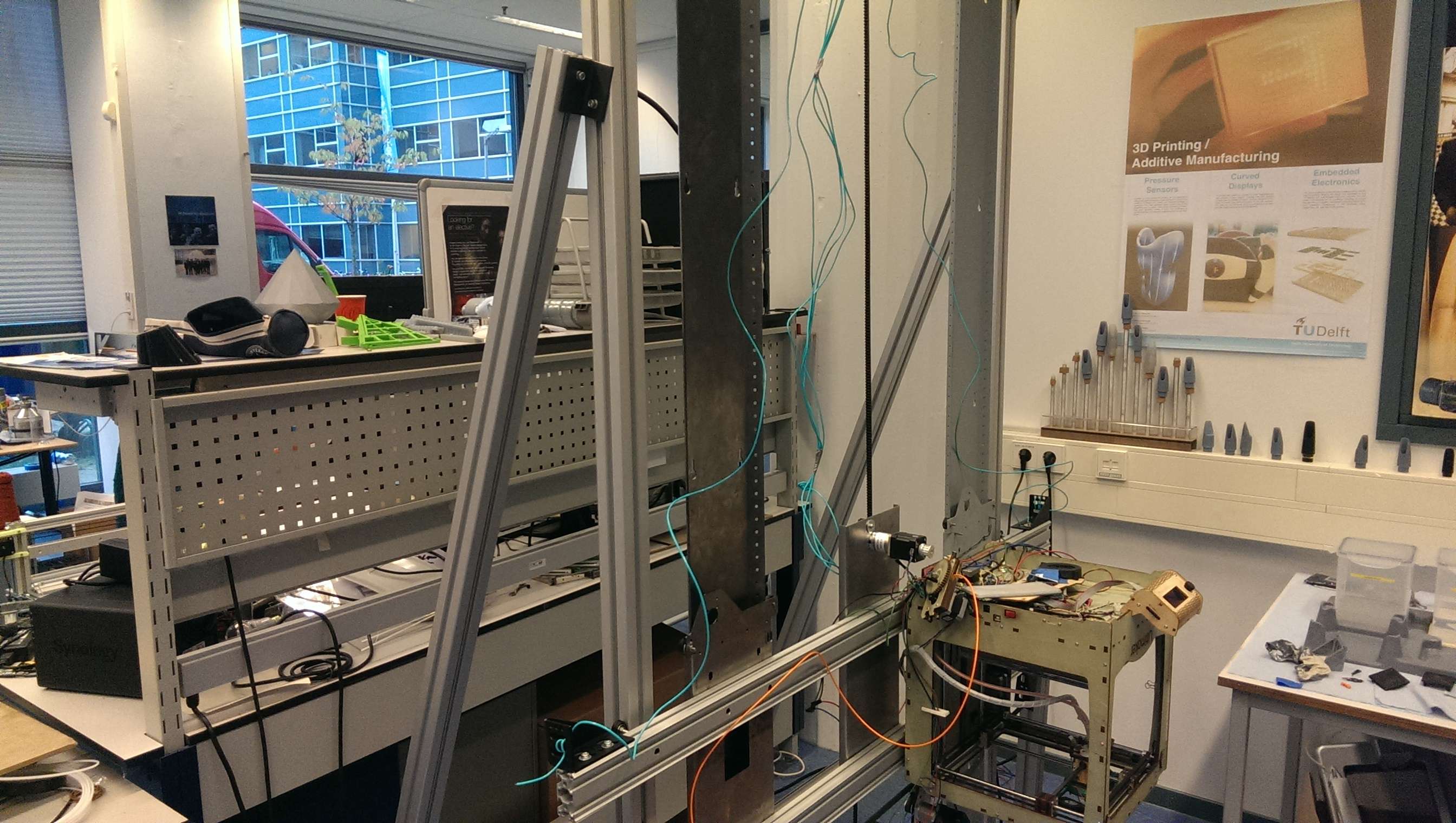
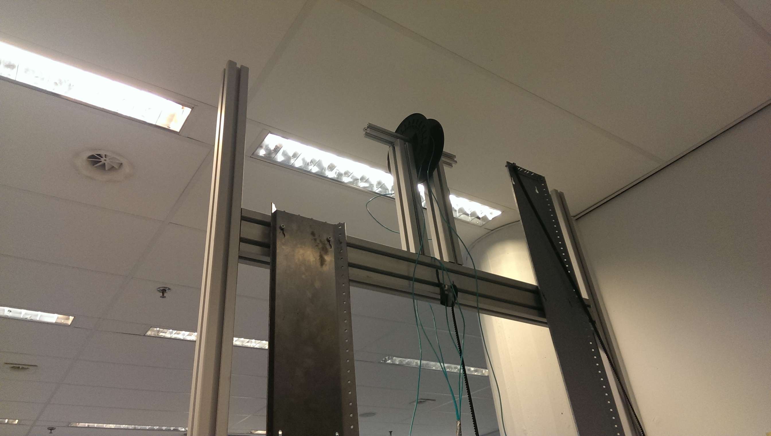
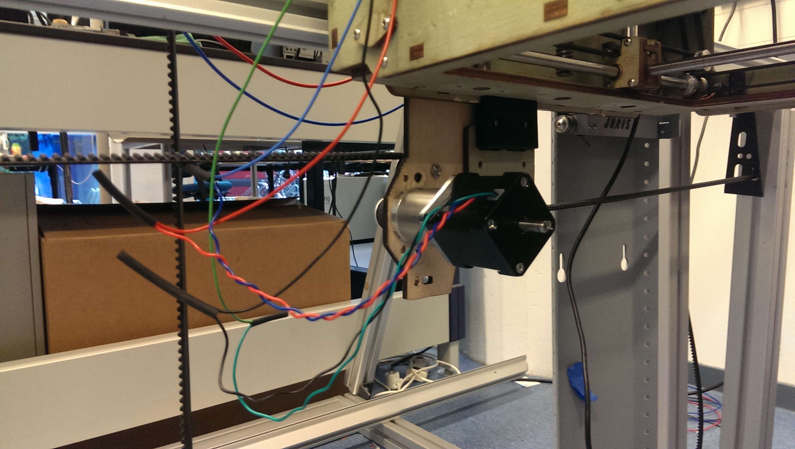
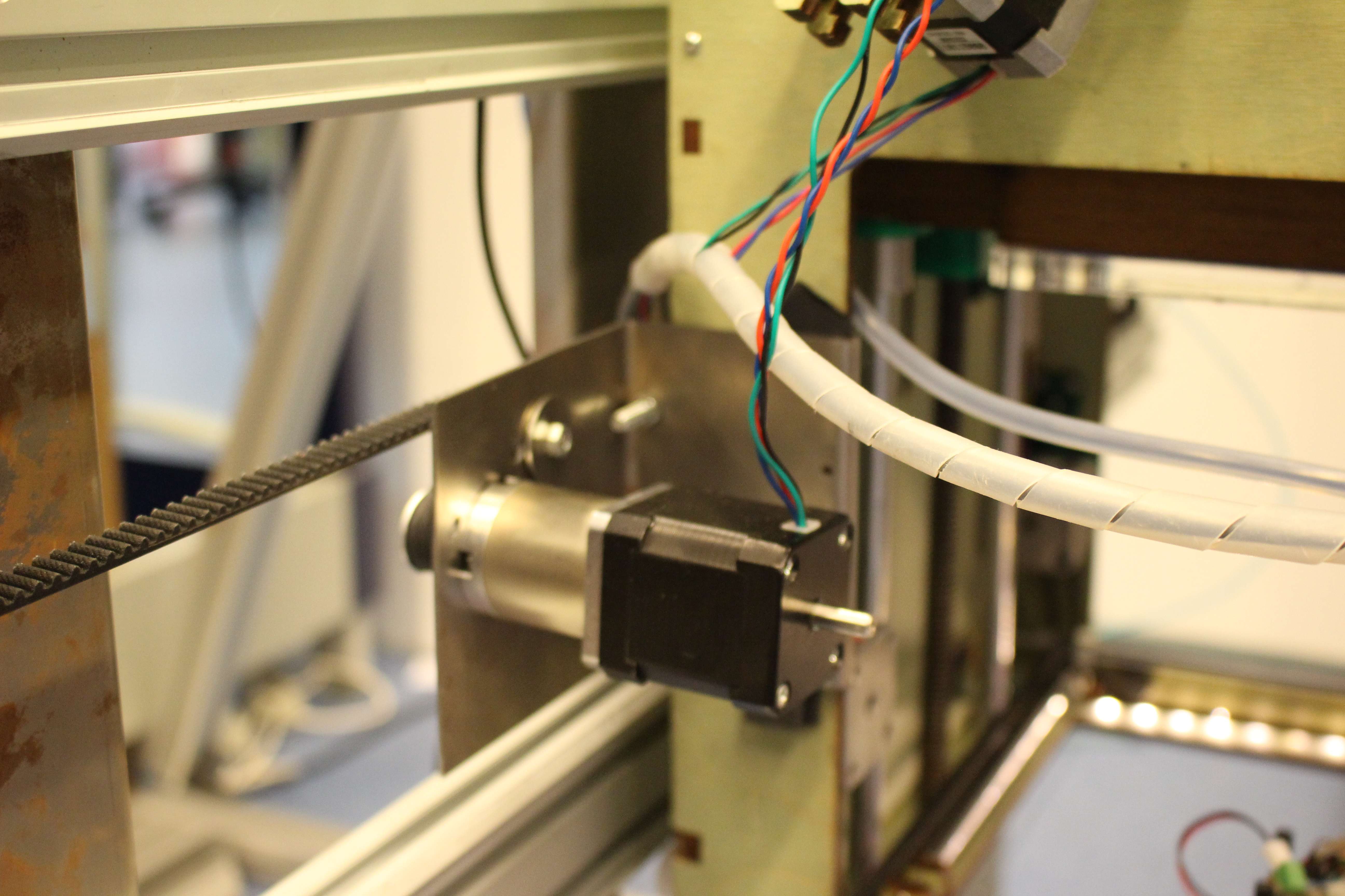
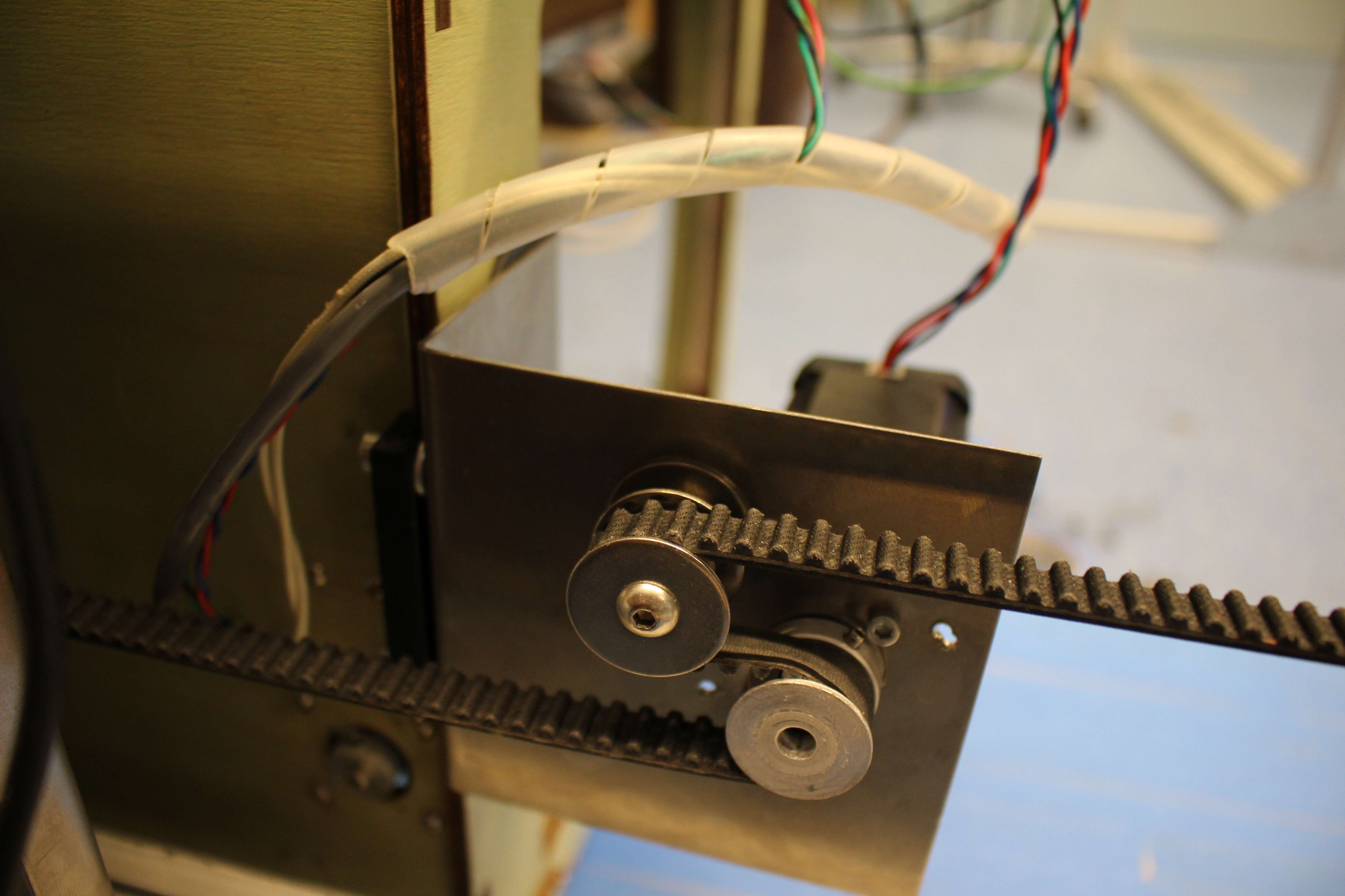
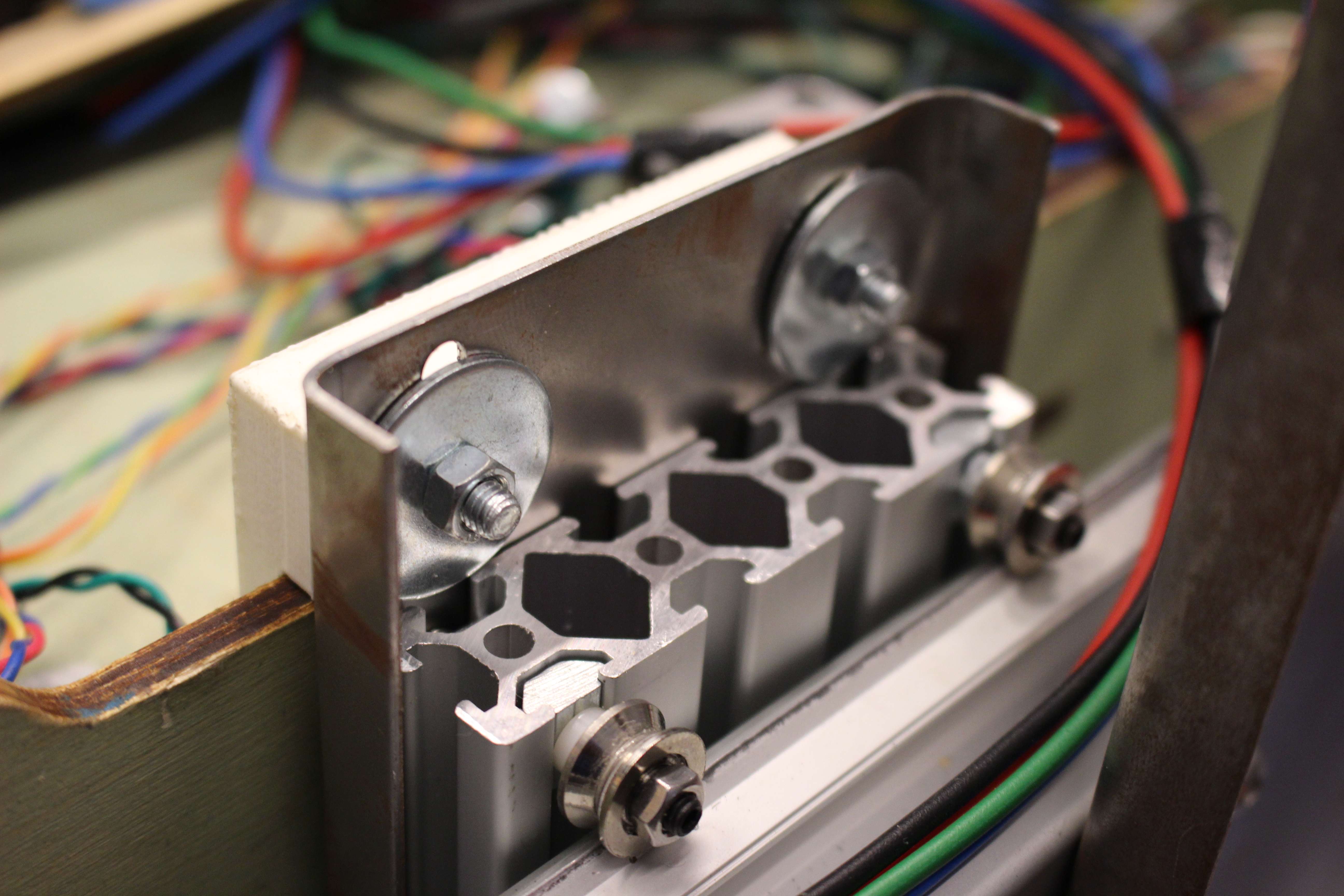
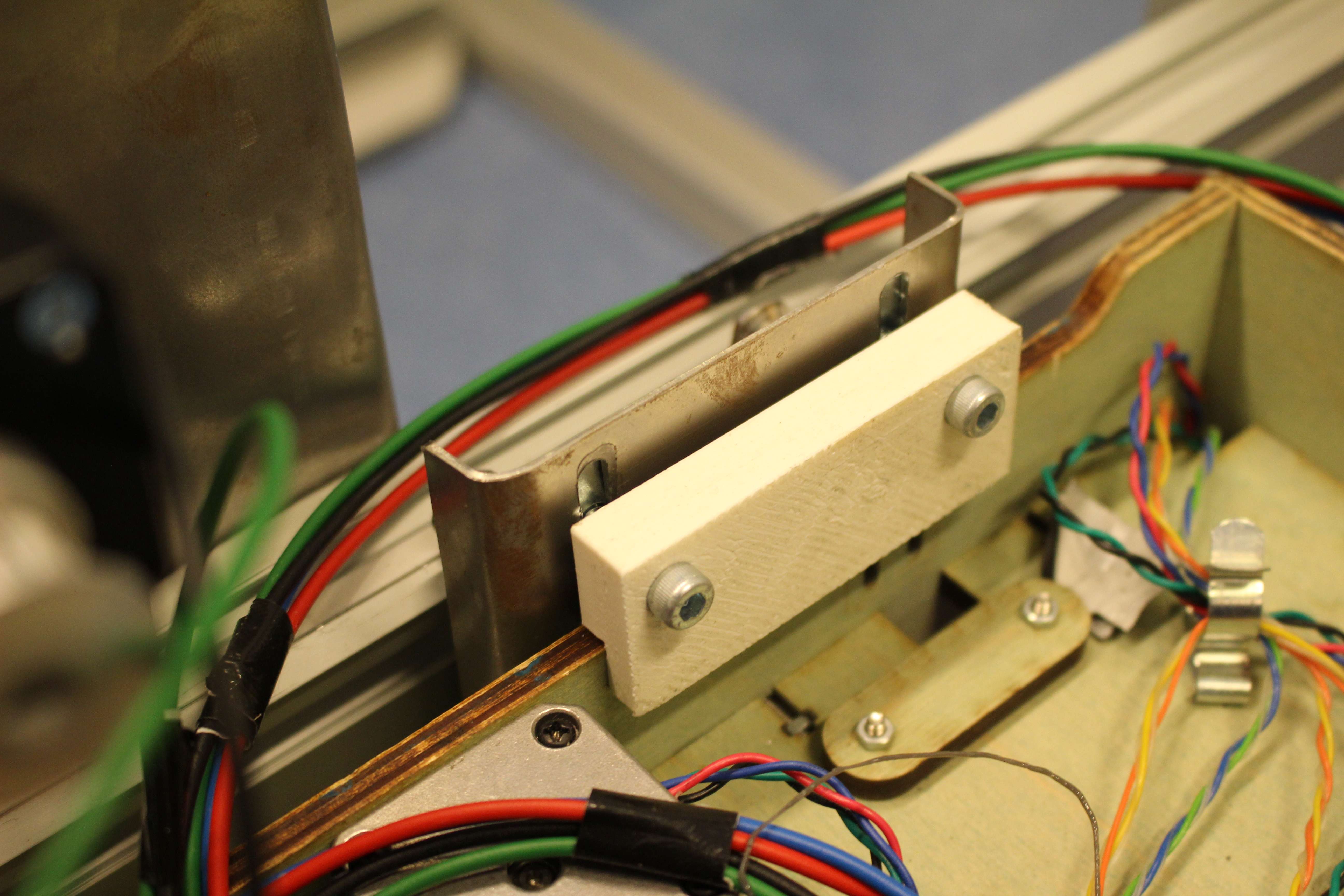
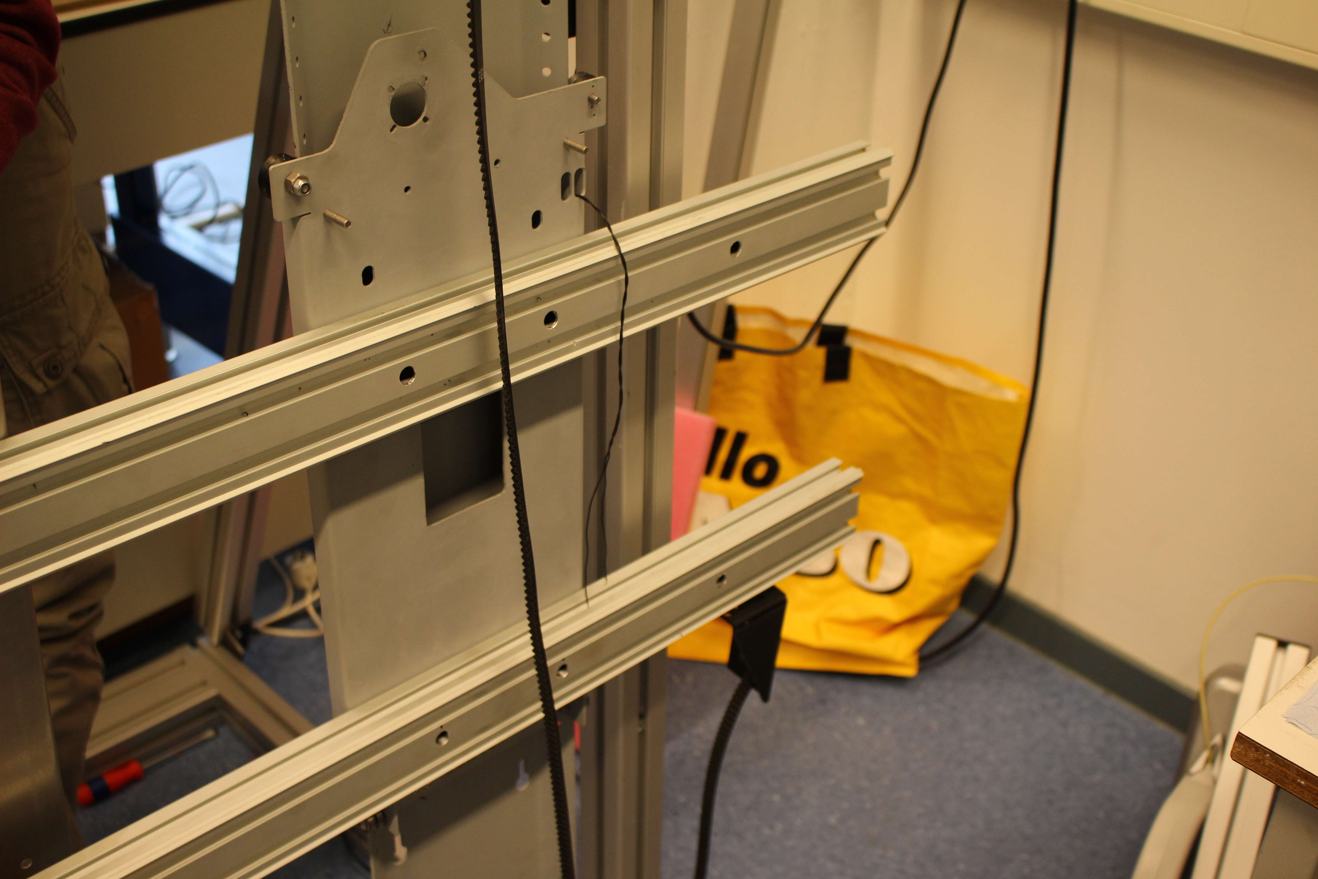
There are a lot of changes that can be done on the construction that would improve the printing result. One of the problems we had with the sideways movement of the Ultimaker, is that during movements the printer kept shaking. This can be solved easily by increasing the distance between each pair of wheels moving on the rail. Additional to this the width on which the printer is clamped, should be increased throughout the complete height of the construction. This can be done by using a steel sheet, that covers the back of the Ultimaker. A wooden plate won’t work, as it will bend and stretch because of the weight of the printer. When we used a wooden plate to mount the printer onto the rail, the holes that hold the wheels became bigger. This caused the Ultimaker to derail multiple times.

constructie.

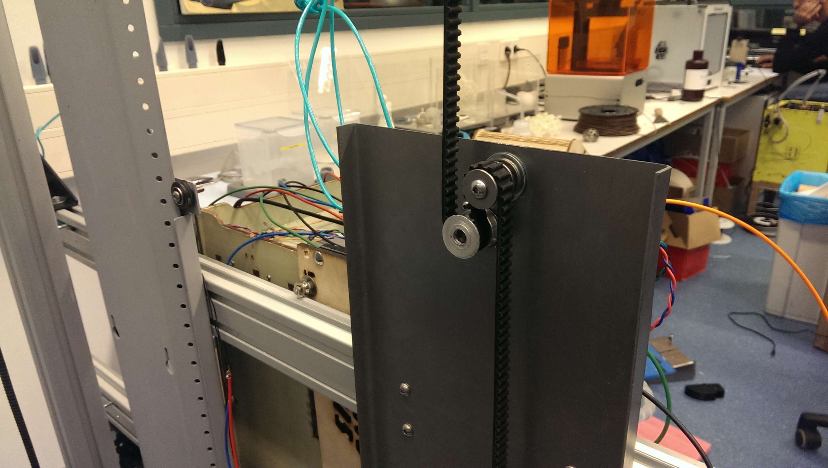
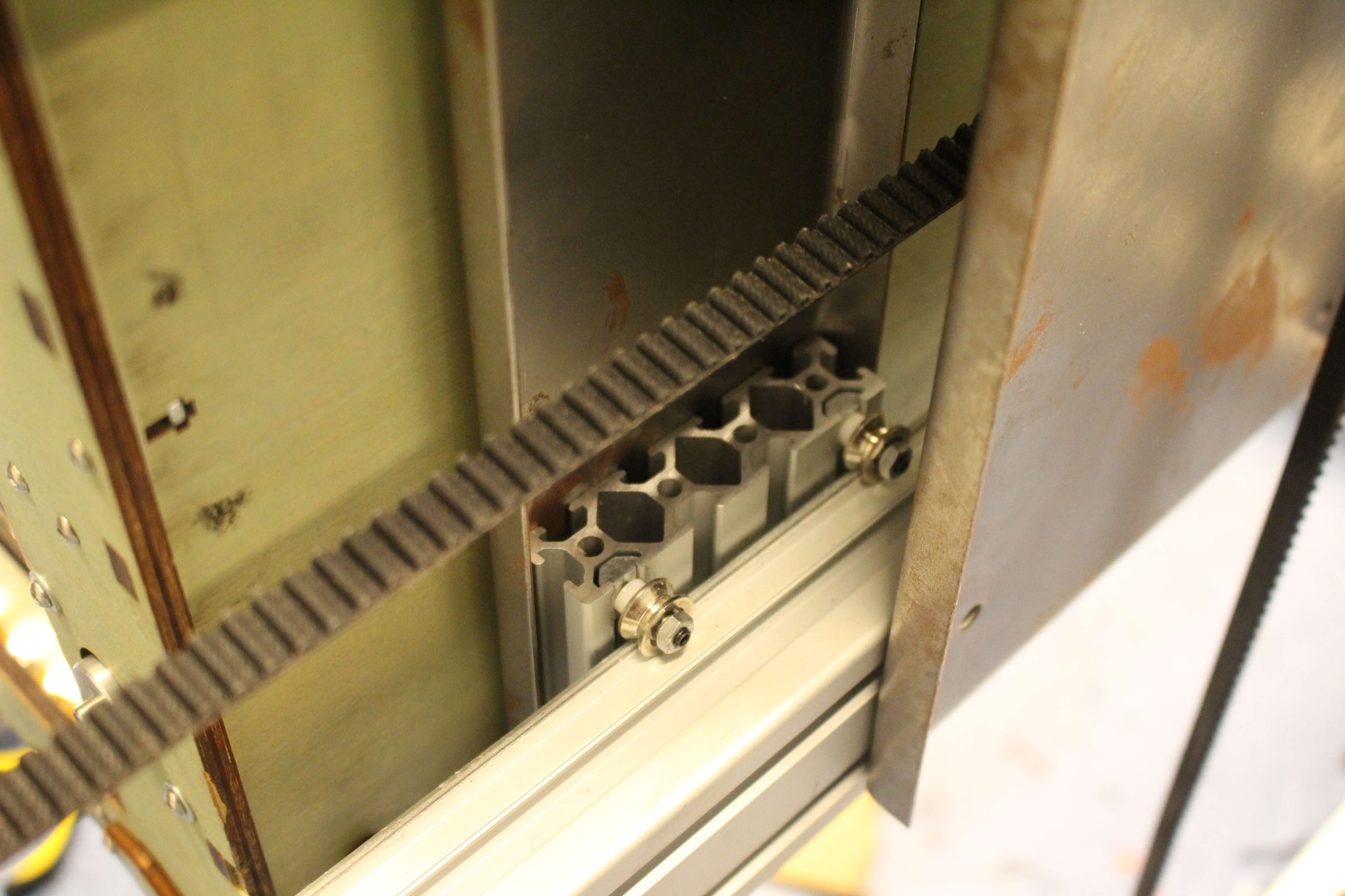
But the biggest problem with the sideways movement was the accuracy. For example, if the printer moved 200 mm to the left and should move 200 mm to the right, it wouldn’t always return to the exact same place. This can be solved by tying the belt tighter.  To do this you could design a system in which you hold one end of the belt and twist it until the belt is very tight. But it would be better not to use a rubber belt for the horizontal movements, especially when covering bigger distances. This because of the fact that, an elastic material, always will bend through because of its own weight, which causes the gear to loose grip. It would be better to have the tooth on rail itself. If these two problems would be solved it would be easier to move the printer on a higher pace, then we were able to. Other things that improve sideways movements:

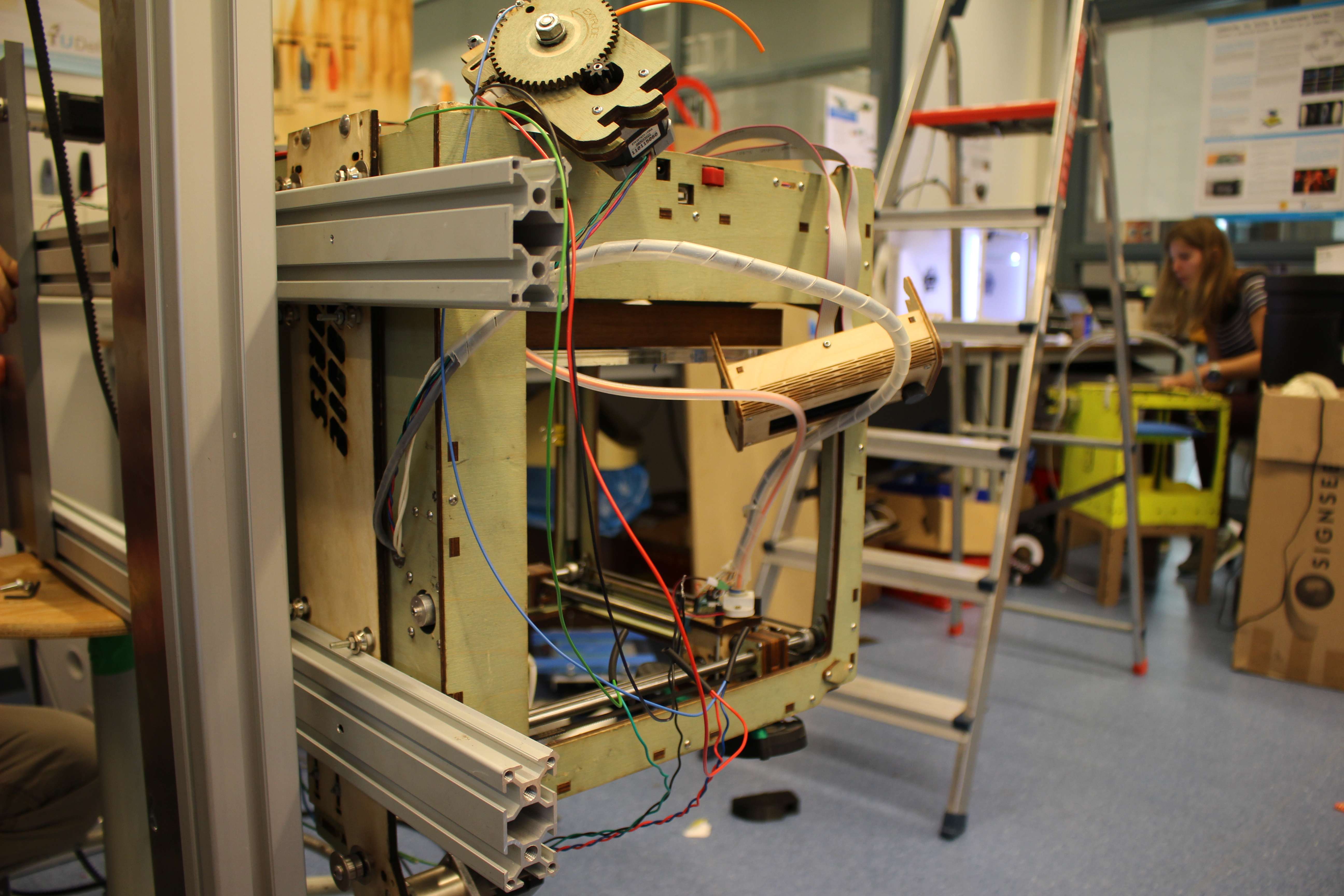
  • using bearing wheels and not metal wheels
  • mounting the stepper motor in a way it won’t be able to vibrate.
  • the less weight there is to be moved, the better.

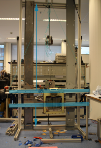
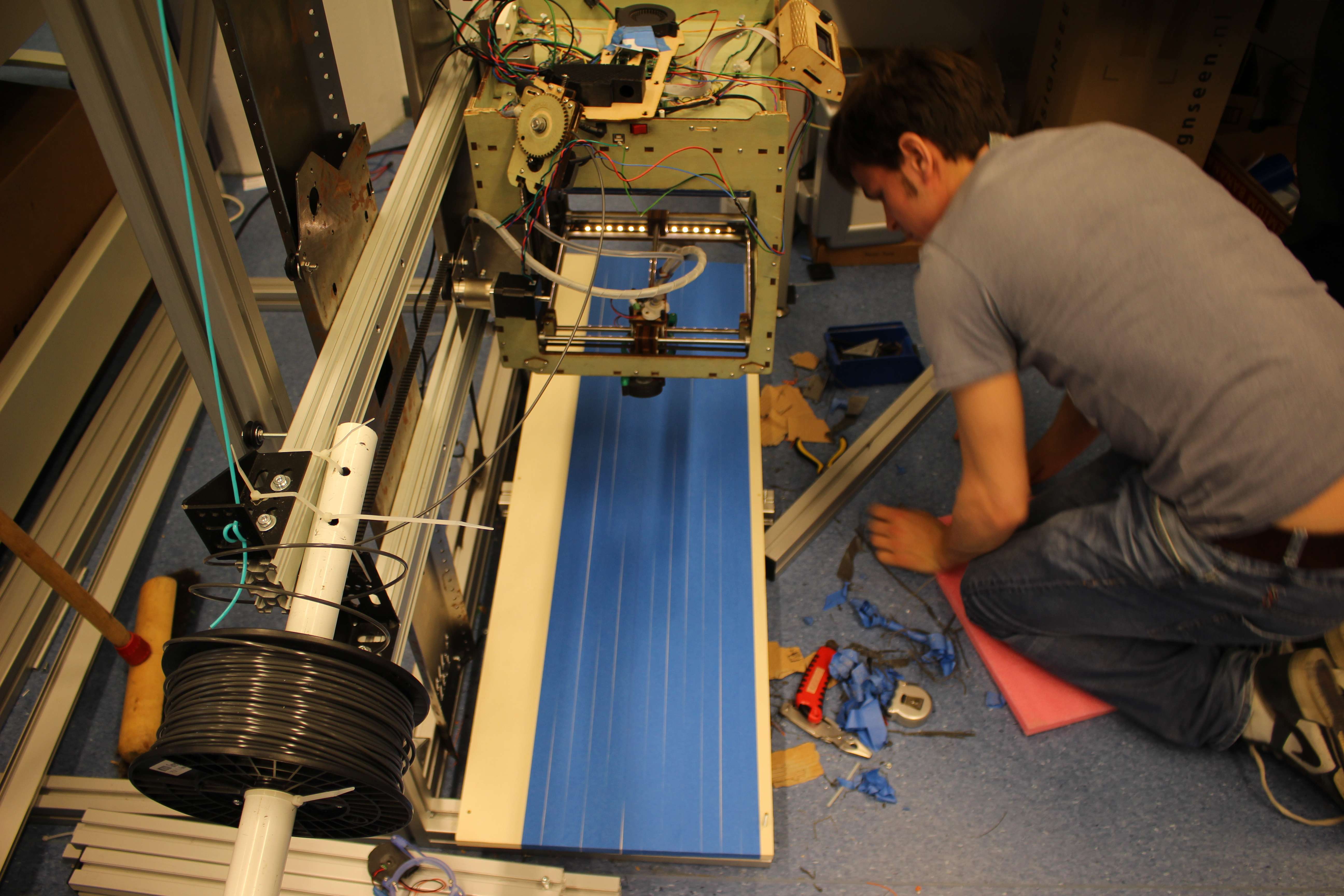
An other big improvement that we would have liked to do, is using a stronger stepper motor with a stronger transmission. This would have made the counterweight, which is quit dangerous, dispensable. Removing the counterweight, makes it possible to put the installation against the wall. Something that would have made life easier for us, would have been to be able to adjust the print bed in an easy way. A nice way to do this would be: lifting the bed straight up to eye level to adjust it, without having to lay down on the ground,  whereupon you move the bed back to the ground.


Possible improvements in the software

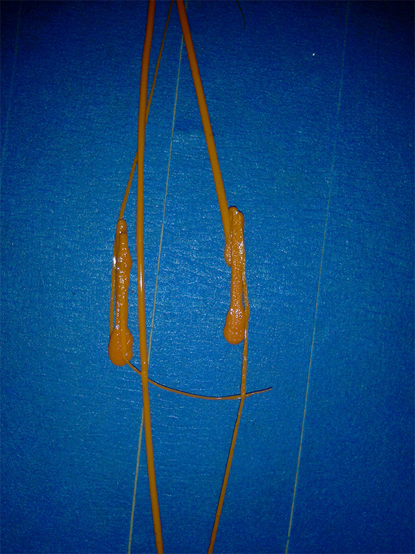
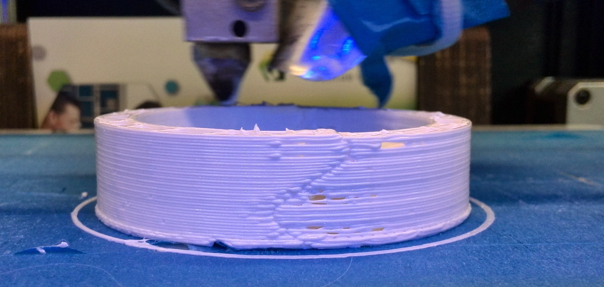
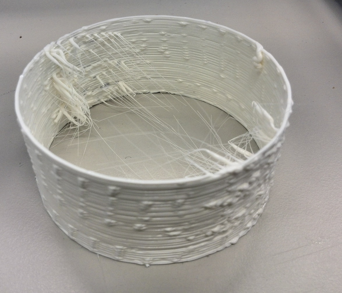
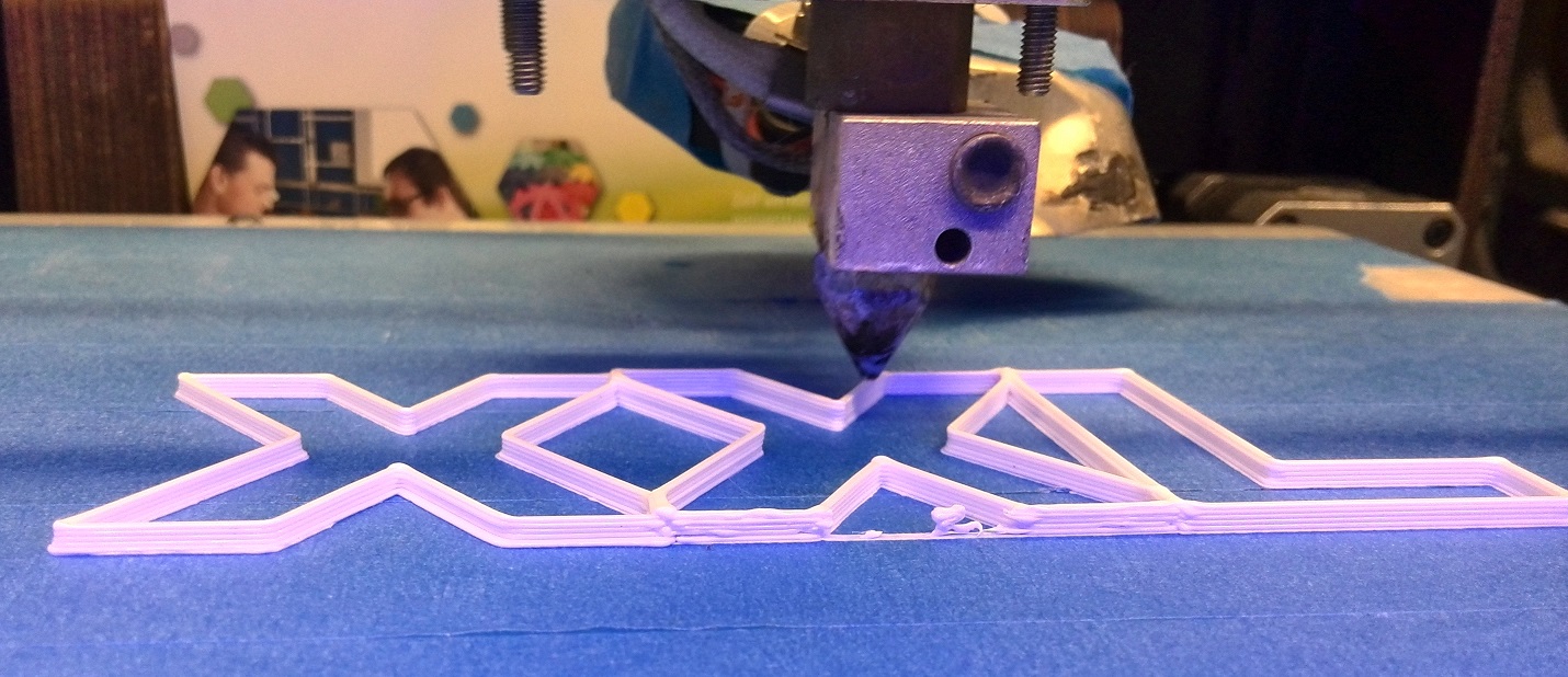
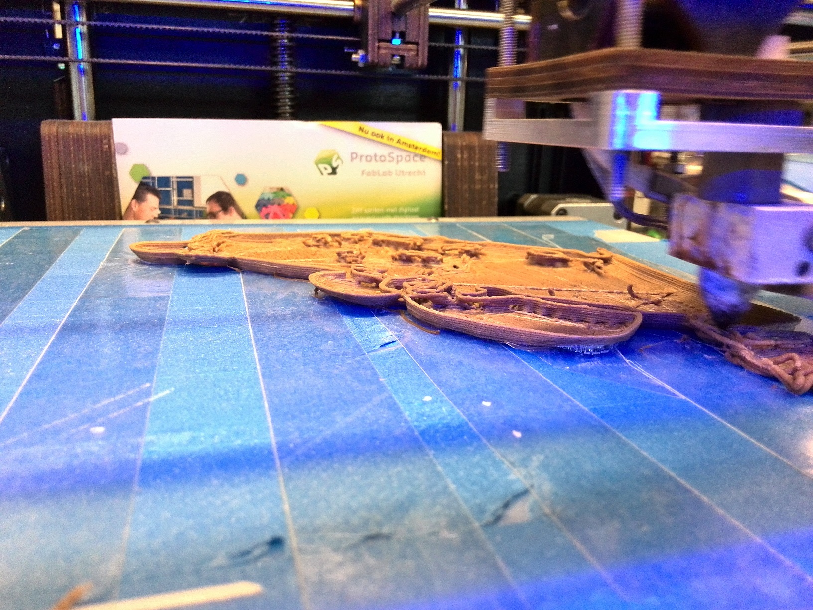
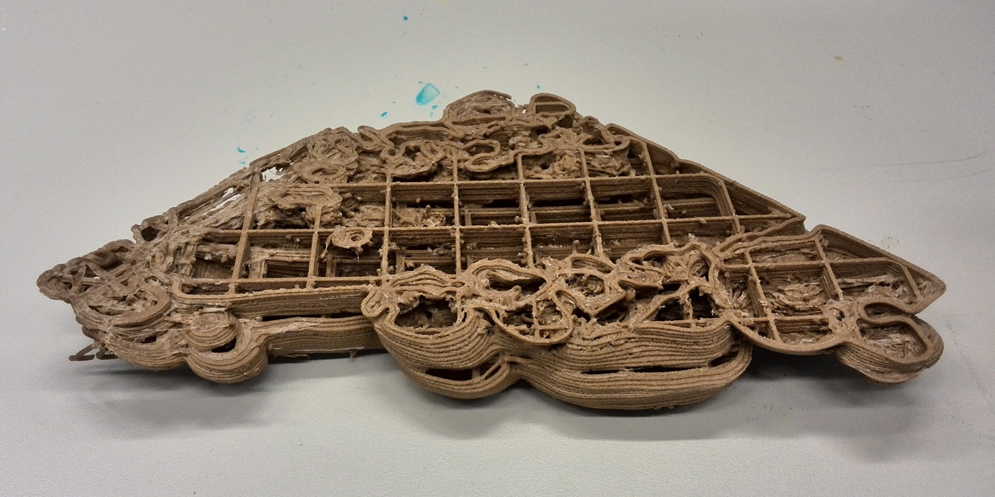
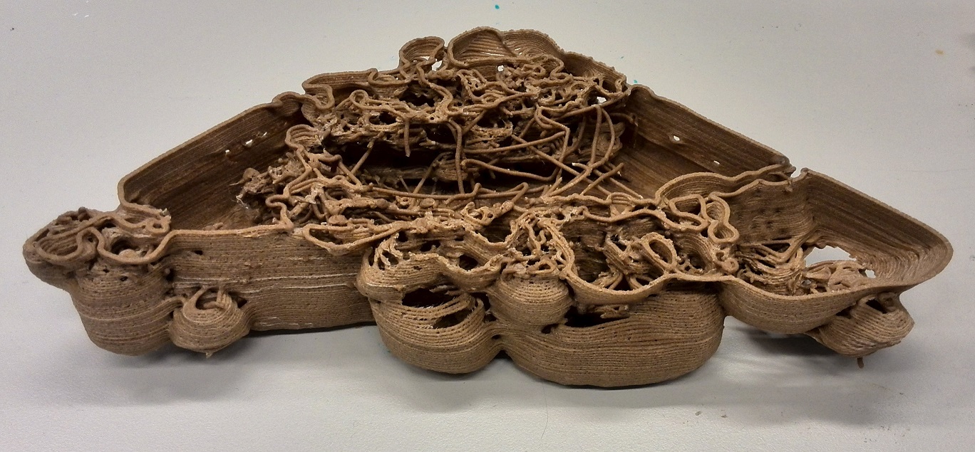
Concerning the software, the most important improvement would be to reduce the retraction. During the last few days of printing, we saw that the filament got stuck occasionally while printing. This was due to the retraction of the filament which happened during moving the ultimaker over the external x-axis. The current retraction is 20 mm (to reduce the amount of plastic flowing out while the print head is not moving). This however, allows plastic to flow back to a part of the nozzle which is not hot enough to stay liquid, and thus occasionally jamming the nozzle by attaching the filament to the side.

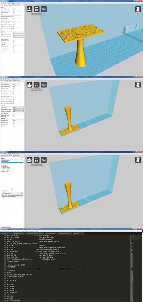
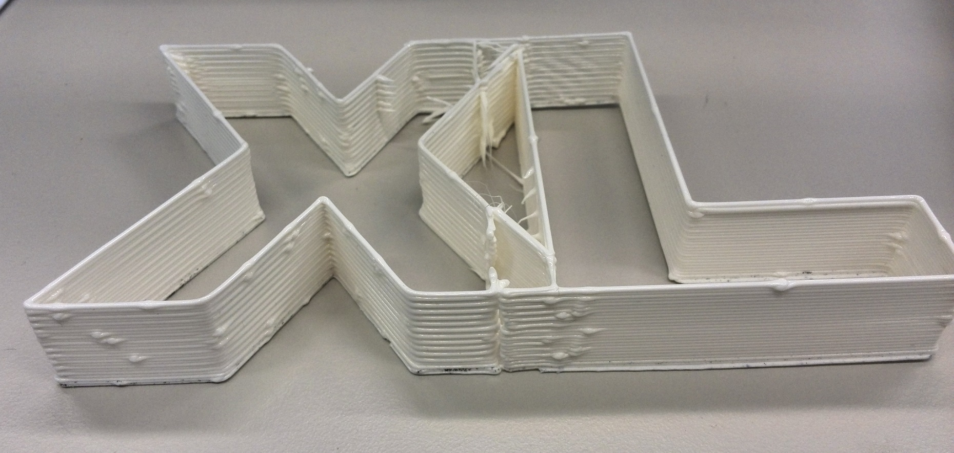
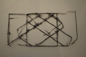
Another improvement would be to use an other slicer than Cura. Cura is only able to do one type of infill. While this is enough while printing small parts, the type of infill (diagonal lines) means that if the part is large, a lot of movement in the x-axis is required. We saw that during printing with an infill, this will cause the Ultimaker to move left and right during printing of each line of the infill at the edge of the printable area, which takes a long time.

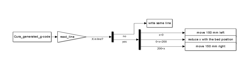
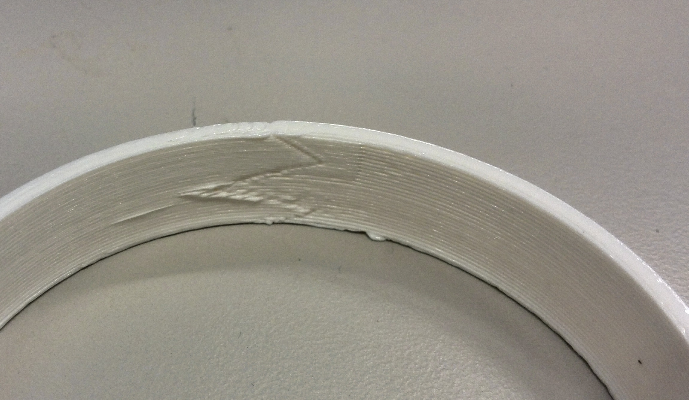
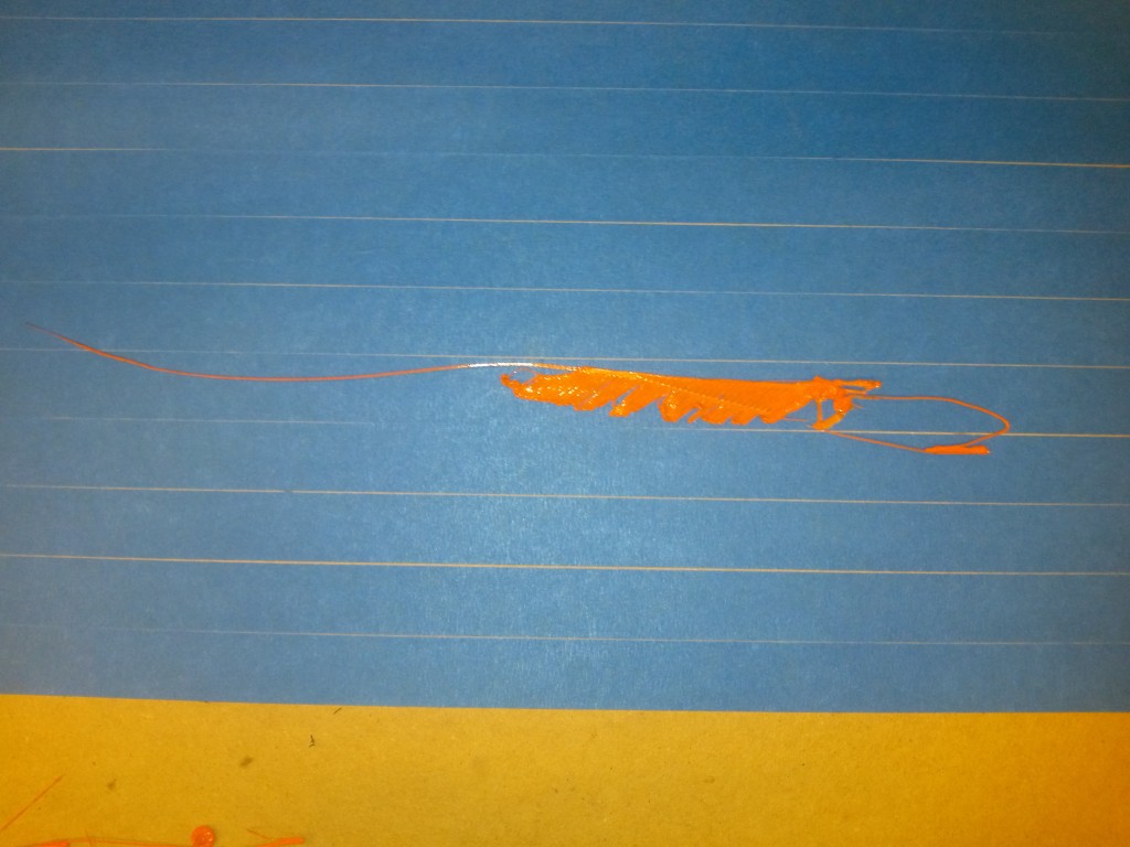
A third improvement would be moving the print head slightly when moving the Ultimaker to completely remove the plastic flowing on the printed part. The easiest possible movement would be to make the print head move slightly to the inside of the part. Doing this will require the plugin to either know what is the inside of the part, or to assume which side is in based on the place of the printing bed. A last improvement would be to add a fix to the code which allows printing of long straight lines. As mentioned before, if the Ultimaker needs to move twice during a single line, it will move, but it will skip printing this part.

Possible improvement for the printing speed

As explained in other posts the printing time of a single layer with this modified Ultimaker wasn’t quite as fast as we would have liked. The motor on the external X-axis wasn’t able to move as fast as we would like due to various reasons, so we started thinking in terms of making the printing more efficient. When observing the printing process of a layer you could see the printer didn’t always follow the most efficient route while moving itself over the X-axis before going up a layer. With the earlier found and explained method of dividing a model into different parts and thus avoiding unnecessary (slow) movement the whole printing process could be made faster.

While we had this working almost flawlessly on a single unmodified Ultimaker, it doesn’t quite work well yet with the plugin that is needed to modify the code for a larger printing range and it would require a few days of implementing those things together and then testing it.

Plugin functionality

plugin logic

Since the plugin is finished, we will explain how it works. The plugin processes the cura generated g-code. The first thing it does, is read the line. If the line includes “LAYER”, a line containing “=====” is written, after which the layer line is written.

If the line contains a “X”, the value of x and e is read and stored in variables. If the x is lower than 0 or higher than 200, the bed moves 150mm, else the value of the bed position is reduced from the value of x, and the line with the new x value is written.

The sequence of moving the bed consists of first retracting the filament, switching to the second extruder (which controlls the external x-axis), moving 150mm while moving the internal x-axis to the other direction, switching back to the first extruder, and undoing the retraction. In order to reduce the amount of errors, the extruded values are zero’ed before retracting and moving, and restored at the end of the sequence (by using the earlier read value of e).

the limitation of this is that it is only possible to move to the left or right one step. If the x-coordinate increases more than 150 (because the model contains a long straight line), the generated code will not be correct.

Required steps to print

Since the project is almost over, and the ultimaker xxl is finished and (almost) fully functional, we will explain the steps required to print with this modified Ultimaker.

The first thing to do is to load the file you want to print into cura. This file does not have to be modified or split in any way, this will be done by the plugin. The only requirements the model has to be printable is that it can’t contain straight lines longer than 150 mm (however, slightly curved lines are no problem) and that the model can’t have large overhangs.

After importing the model in cura (increase printbed size if it doesn’t fit), the part can be rotated, scaled and moved. The part has to start at the left side of the printable area to reduce the required print time and reduce the risk of errors during printing.

The next step is to enable the required plugin in the plugin menu (and, if it isn’t available, to place the plugin in the plugin folder). The plugin converts the cura generated g-code to code that is able to controll both the internal and external x-axes. Make sure the plugin is displayed on the lower side of the menu.

After enabling the plugin, the g-code can be generated by clicking the save toolpath or toolpath to sd button on the top side of the screen. If you want to check that the plugin functioned correctly, it is possible to open the generated g-code in a text editor and look for lines filled with “========”. If these lines are present, the plugin functioned correctly.

The final step is to manually move the ultimaker to the left-most position on the external axis. This due to the lack of end stop for the external x-axis. After this is done, the file can be selected and the printing begins.Untitled-2

Printing a model in parts

As explained in other posts the printing time of a single layer with this modified Ultimaker wasn’t quite the fastest. The motor on the external X-axis wasn’t able to move as fast as we would like so we started thinking in terms of making the printing more efficient and making the most out a position the printer would be in.

When observing the printing process we had noted the printer would make a lot of unnecessary movements from left to right and back, before going up a layer. We figured we could save time if we found a way to tell the printer first to print everything in range on the left side and once that was done, move over to the middle or right side depending on the width of the model to print.
Because of our limited time before the Science Fair and not having found the perfect general printing settings yet, a part of the team kept working on the actual setup, while others started testing these ideas on a standalone Ultimaker Original.
Luckily the implementation didn’t require a lot of coding or new plugins to be written. It turned out that by changing the machine settings in Cura from 1 to 2 extruders a g-code was written that made an Ultimaker Original printer with 1 extruder print models in certain parts. An other requirement though was that the model had been split into different parts which had to be made into stl’s and separately imported into Cura. By doing this it allowed Cura to understand how the partition was made and what to print first before moving to an other part.
screenshot.310
After some tests this seemed successful as you can see in this video:
[youtube]https://www.youtube.com/watch?v=Jw2CjWDdSUA[/youtube]
First the printer is printing parts on the left side, before moving on to the right side, back left etc.
Because you’re making a print consisting of multiple parts we were afraid this might increase the weakness of the print, especially around the welt where 2 parts met. Therefor we also tried splitting the objects not with a straight line but with other curves, from serrated shapes to waves:
2014-10-23 12.42.51 2014-10-23 15.56.31
This proved to increase the strength of the objected when we tried to break it with force.
During further tests we ran into a problem when trying to print only the outline of an object. When switching to the other part, the printer often picked the opposite side which meant it had to stop printing, move and start printing again at a different Y coordinate. This resulted often in a mess of inaccurate ends/starts of lines.
2014-10-23 13.59.12
A solution to this seemed to either give the object an (low percentage) infill, or thicker wall or find better positioning for the cuts of different parts.
2014-10-24 11.05.41 2014-10-24 11.33.20
Finally we started running tests with models split into 3 parts and Cura set to 3 extruders.
While a lot of the previous found knowledge was applicable, we ran into new problem that hadn’t come up yet with only 2 parts.
3 parts meant different orders of printing those parts were possible and soon enough it showed our printer wasn’t clever enough to pick the most efficient order of printing.
screenshot.309 2014-10-24 11.57.48
For some reason it would always start with the middle X, move to the L, then all the way to the left X before going back to the middle etc.
So far we haven’t found a way yet to make it start on a certain side and then moving back in reverse order once it had finished a complete layer; left>middle>right (up a layer) right>middle>left (up a layer) etc.
[youtube]https://www.youtube.com/watch?v=G4L7U3bBxcU[/youtube]

Construction and movements in week 4

After four weeks the project has come to an end and we can say that we have achieved most of our goals.

The printer is working correctly, precisely and better than we had expected. The maximum size that we can print with our particular installation is approximately 1000*800*200 mm. With some simple adjustments to the frame, we would be able to print up to 2000 mm high.

How the mechanics  look now compared to two weeks ago:

We have changed the place of steppermotor which moves the Ultimaker along the bigger X-axis. This way we are now able to print on the total Y-axis of the Ultimaker

IMAG0586 IMG_7006 IMG_6989

An other thing we have changed is the printbed. In the first three weeks we weren’t able to adjust the height of the bed as it was resting on three beams. We didn’t need a real precise flat bed, as we didn’t werent able to come close to the point that the print was effected by the bed. The printer itself was the biggest problem, for failed print. As the printer became more precise we needed find an adjustable (very) flat bed. We used a 12 mm triplex. We drilled 6 holes in the wood and used screws and bolts to adjust it. We would have prefered to use thick plexiglas which is very expensive.

IMG_7020


And as we told in an earlier post we also changed the way the Ultimaker was attached to the horizontal tail. We replaced the earlier used wooden plate for a steel plate. The reason for this was that the holes in which the rails were fixed, got bigger. And because of this the printer fall off the rail a couple of times. The resulting product can be seen in the picture beneath.

IMG_6988 IMG_7014 IMG_6986 IMG_6835_Kopie


This were the major adjustments in the construction of the installation. For the rest there were some little tweaks here and there.


Adjusting the printer

As the mechanical parts were installed and working, it was time to calibrate the printer to print smooth and accurate objects. As we encountered problems with the additional X-axis we decided to start working with only one x-axis. We replaced the inner X-axis with the outer axis.

This brought different problems to light. The normal acceleration of the printer head was to high for the external x-axis. The stepper motor kept slipping and moved further than it should. With every move the x-axis made, the difference with the layer beneath  became bigger.
It also didn’t help the fact that the belt on which the stepper motor moves, wasn’t tense enough.

We also had a problem with the amount of steps the stepper motor on the bigger x-axis made compared to the y-axis stepper motor inside the Ultimaker. When we noticed this problem while printing, we tried to print a square to confirm our observation. And our observation were confirmed when the Ultimaker made a rectangle instead of a square. To solve this problem we adjusted some numbers in the firmware of the printer.


IMG_6997

Here you see a test print. You see two rectangles with overlap, because of a shift that happend.

A third problem  we encountered was that the internal x-axis kept moving a little when the printer shifted from left to right and back again. Because there was no electric single to the stepper motor, there was no ‘brake’ on this axis.

We didn’t continue with the idea of working with only one x-axis, even with the fact it was very promising. As it is eventually the plan to make multiple printers work together two axes per printer are effective.

So we continued with the original plan: getting the printer to print while using two x-axes.


Week 3

Afgelopen donderdag is Dolf weer langs om te kijken hoe het ging. Een heldere planning maken blijft erg lastig met dit project. Vanwege het expirimentele karakter is het moeilijk inschatten hoeveel tijd iets in beslag gaat nemen en waar je tegenaan zult lopen. Om de komende anderhalve week nog zo veel mogelijk vooruitgang te boeken hebben we een blokkenschema gemaakt om een overzicht te krijgen wat wanneer af moet en waar we nog speling hebben om eventueel op sommige punten nog verder uit te breiden.

Het is voor ons nu om een overweging te maken of ons focussen op één printer die goed werkt langs twee assen, of op het eventueel toevoegen van een tweede printer met een kans dat dit nog niet helemaal werkt.

Verder hebben we ook opnieuw geprobeerd met woodfill te printen. Het was tenslotte één keer eerder goed gegaan. Dit was echter op een print die al deels uit een ander materiaal bestond en met een erg lage materiaal hoogte. Als we direct op het printbed printen, hecht de woodfill niet goed en trekt het krom bij het afkoelen.

IMG_6797 2014-10-17 10.22.47

Een redelijke oplossing hiervoor is dubbelzijdig tape. Hier zijn we achter gekomen door trial and error. Het is nog steeds geen ideale oplossing, omdat de tape zelfs te goed aan de print plakt dat het erg moeilijk van het printbed loskomt en daarna opnieuw getaped moet worden. We hebben echter geen verwarmd printbed, dus er is momenteel geen andere mogelijkheid.

Vervolgens hebben we proefprinten gemaakt van het kunstwerk van de Rietveld Academie student met wie we contact hebben over het printen van zijn werk. De aangeleverde bestanden voldeden echter niet aan de eisen om goed geprint te kunnen worden met een Ultimaker. Het zat vol gaten, dus we hebben dit bewerkt zodat het aantal gaten gereduceerd is en het hopelijk nog voldoet aan de eisen van project vanuit de Rietveld Academie. Ook dit gaf nog geen ideaal resultaat, maar komt al dichter in de buurt van het beoogde resultaat.

2014-10-20 11.01.50 2014-10-20 11.02.05

Verder zijn we bezig geweest met het maken van een staalplaat voor de ophanging van de achterkant van de Ultimaker aan de de X-assen, want hout bleek niet sterk genoeg en er ontstond te veel speling. Ook is de motor voor de X-assen die onder de Ultimaker hing, met een staalplaatje en een geprint klemmetje naar de zijkant verplaatst. Deze motor kwam namelijk tegen het printbed en de constructie aan.

          IMG_6986

Toen de hele opstelling weer in elkaar gezet was en het testen voortgezet kon worden bleek dat er problemen waren met de beweging in de X richting. Bij het wisselen van extruder vergat de printer namelijk welke hoeveelheid hij eerder al opzij was bewogen en verplaatste zich dus te ver. Gelukkig kon dit door Tim in de firmware van de Ultimaker worden aangepast en verholpen worden. Ook bleek er onnauwkeurigheid te onstaan doordat de rubberen tandriem voor de verplaatsing langs de X-as niet geheel strak gespannen was omdat de motor tijdens het printen van een laag van beweegrichting veranderd en de motor dan eerst heel even bezig was deze strak te trekken alvorens zich te verplaatsen.


Wat nog te verbeteren

2014-10-14 09.44.26Gistermiddag waren alle aanpassingen in de constructie doorgevoerd zodat we konden gaan testen. We hebben dus kunnen testen met de ‘dubbele’ x-as. Hierbij ging nog een aantal dingen fout.

Ten eerste was de plaat die we als printbed gebruikte niet vastgemaakt aan de constructie, waardoor deze een beetje krom lag. Daardoor was de afstand tussen de printkop en -bed niet overal evengroot, wat ervoor zorgde dat de print de ene keer niet hechtte en de printkop de andere keer in de houtplaat duwde. Untitled-2

Het volgende probleem was dat de afstand om de externe x-as te bewegen niet goed in de code stond. Deze afstand moet bepaald worden door ‘trial and error’, doordat de overbrenging tussen de motor en de as niet bekend is. De hierdoor ontstane afwijking is te zien in de tweede foto.

Het laatste probleem was dat er in de tandriem van de externe x-as een beetje speling zit doordat deze riem niet strak gespannen is. Dit zorgt ervoor dat de printer als hij opzij moet bewegen, niet dezelfde hoeveelheid heen en terug beweegt.


De constructie en aandrijving

De installatie bestaat uit de volgende onderdelen:

  • Het frame
  • de verticale rails
  • de horizontale geleiders
  • een bevestigingsplaatje voor de Ultimaker
  • de Ultimaker
  • het printbed
  • contragewicht

Het frame is gemaakt van een bepaald alumiumprofielen systeem. De verschillende balken worden op dezelfde manier aan elkaar vastgemaakt. Het is 120 cm breed en 290 cm hoog.

IMAG0581

Op het frame zijn de verticale rails bevestigd. Deze zijn ons door Joris ter beschikking gesteld.

Vervolgens zijn op de vericale rails, de twee horizontale rails bevestigd.

IMG_6835_Kopie

Om de printer over de horizontale rails te laten lopen hebben we een plankje met 8 v-wieltjes er aan vastgemaakt.

IMG_6836_kopie     IMG_6837_Kopie     IMG_6838_kopie

Verder hebben we nog het printbed en een katrol met een contragewicht.

IMAG0583 IMAG0584

Bij de benodigde bewegingen maken we gebruik van stappenmotors. Voor de verticale beweging hebben we een stappenmotor aan een stalen plaatje bevestigd en vervolgens aan de horizontale rails vastgemaakt. Deze motor wordt geholpen door een een contragewicht van ongeveer 15 kg.

IMAG0588   IMAG0591

De stappenmotor die de beweging over de vergrote x-as regelt, is onder de Ultimaker bevestigd.

IMAG0586